Studio 5000 Logix Designer is Rockwell Automation's primary engineering environment for programming ControlLogix and CompactLogix controllers. In this post we will walk through installing the software and writing your first program step by step.
You will learn what processor firmware is, how to download it from the Rockwell Download Center, how to configure communication in RSLinx Classic and FactoryTalk Linx, how to start a virtual controller in Logix Emulate, and how to write your first program in ladder logic.
This is the second part of our series on Allen-Bradley controllers. If you are not yet familiar with the hardware, start with the post Allen-Bradley Controllers: CompactLogix, ControlLogix, Micro800.
What Is Firmware?
PLC controller firmware is its internal system software (often referred to as the operating system) that manages the basic operation of the device. For Rockwell Automation processors, the firmware version/processor revision must usually match the version of the Studio 5000 Logix Designer software exactly. For example, if we have a controller with firmware version 32, we must also use Studio 5000 software version 32 to program it. New Allen-Bradley controllers often ship with only a basic bootloader and require firmware to be loaded (known as flashing) before first use. To manage and update firmware on Rockwell devices, a dedicated tool called ControlFLASH or its newer version ControlFLASH Plus is used.
Downloading Firmware from the Compatibility & Downloads Center
To download the firmware version we are interested in, we need to enter the keyword Rockwell Automation Download Center in our browser. Once the page opens, click the Find Downloads field.
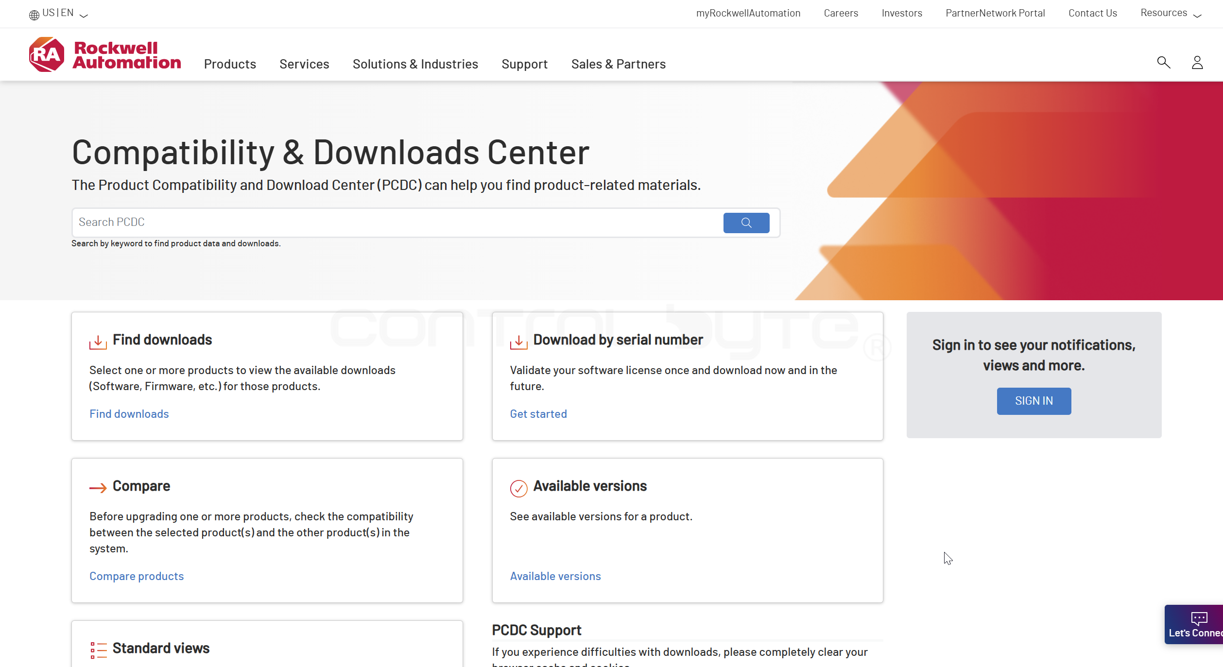
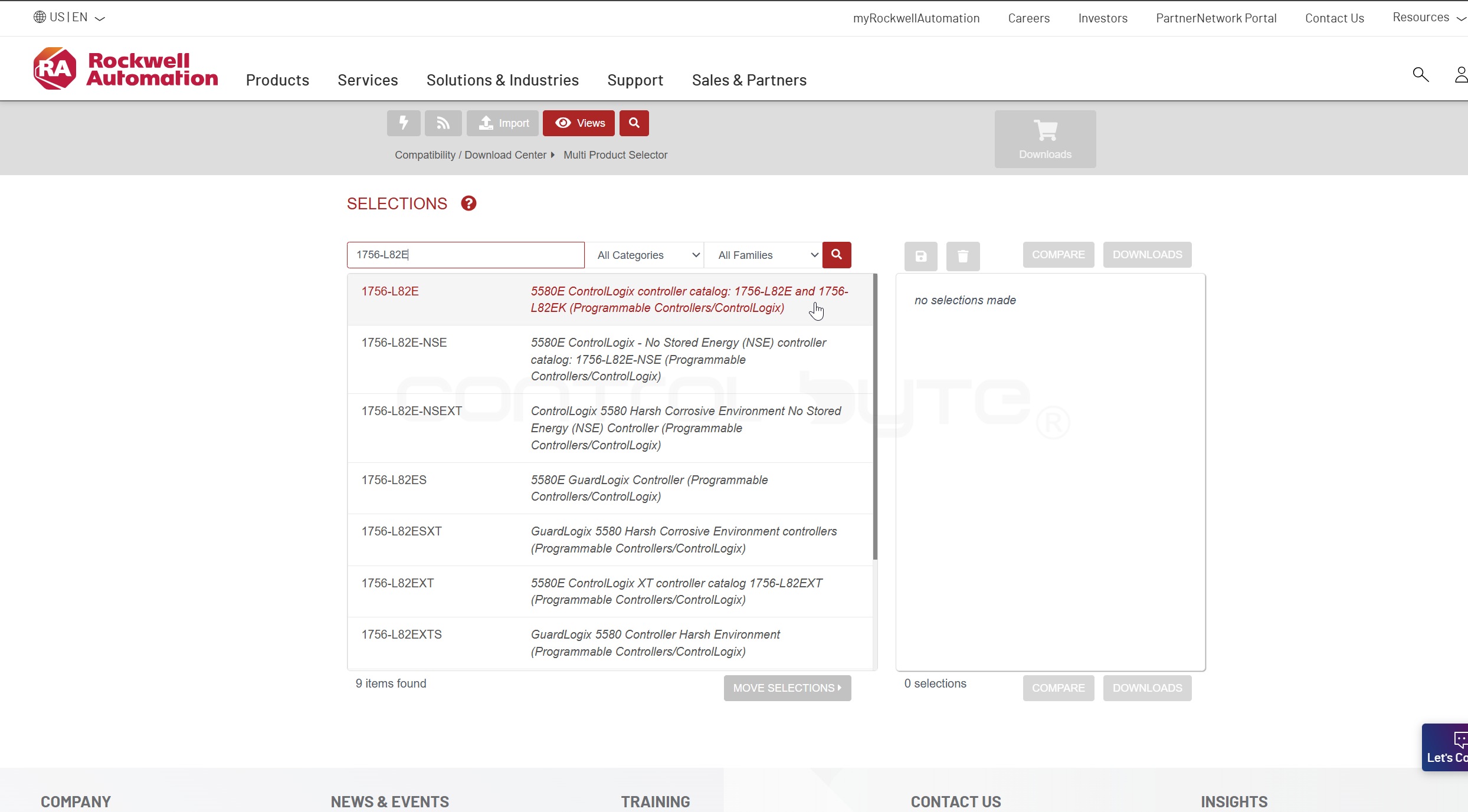
In the field below the Selections heading, enter the name of the processor we are interested in, for example 1756 L82E.
After selecting the processor from the list, the available revisions for download will appear. Next to each revision there is a colored triangle icon that indicates the life status of a given version (Lifecycle).
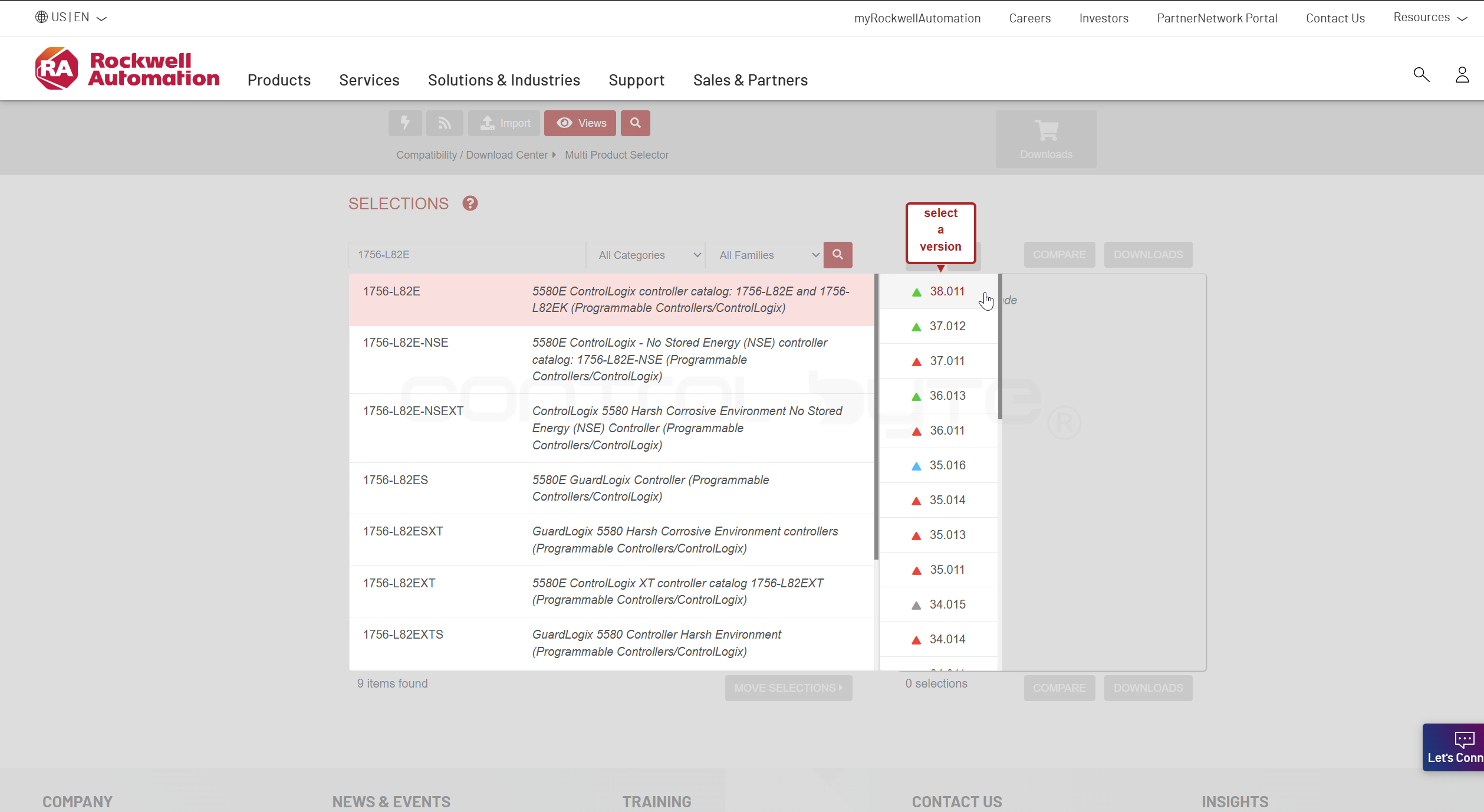
Lifecycle Colors
- Green - the version preferred by the manufacturer. It is considered the most stable, fully tested, and free of known critical defects
- Blue - the latest available version within a given major revision (e.g.
v35) that has not yet received the "Preferred" status. It contains the most recent fixes but may have been on the market for a shorter time than the green version - Red - a warning about a critical defect. Rockwell officially advises against using this version, as it may cause issues such as an unexpected processor shutdown (
Major Fault) or communication problems. It is often accompanied by aPSAdocument (Product Safety Advisory). - Gray - a standard version that is no longer the newest nor specially recommended, but remains available for service purposes or to maintain consistency in older processors
We select the Select Files option.

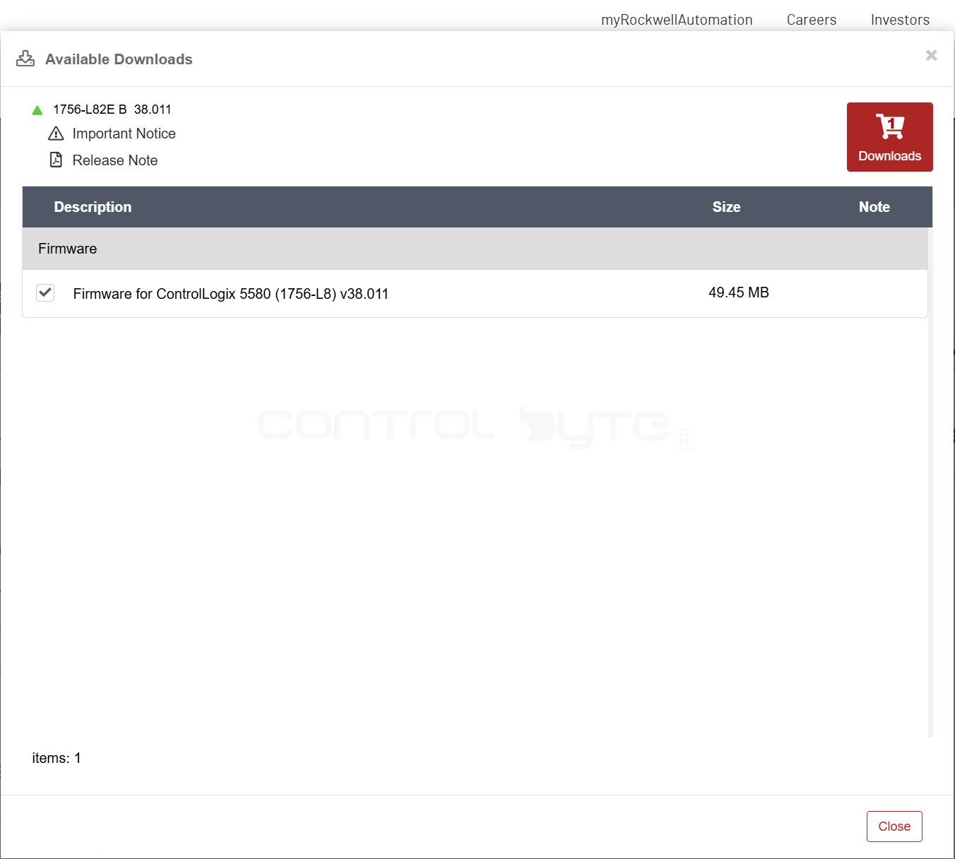
The Available Downloads window will open. We select the firmware we are interested in and click the red Downloads button.
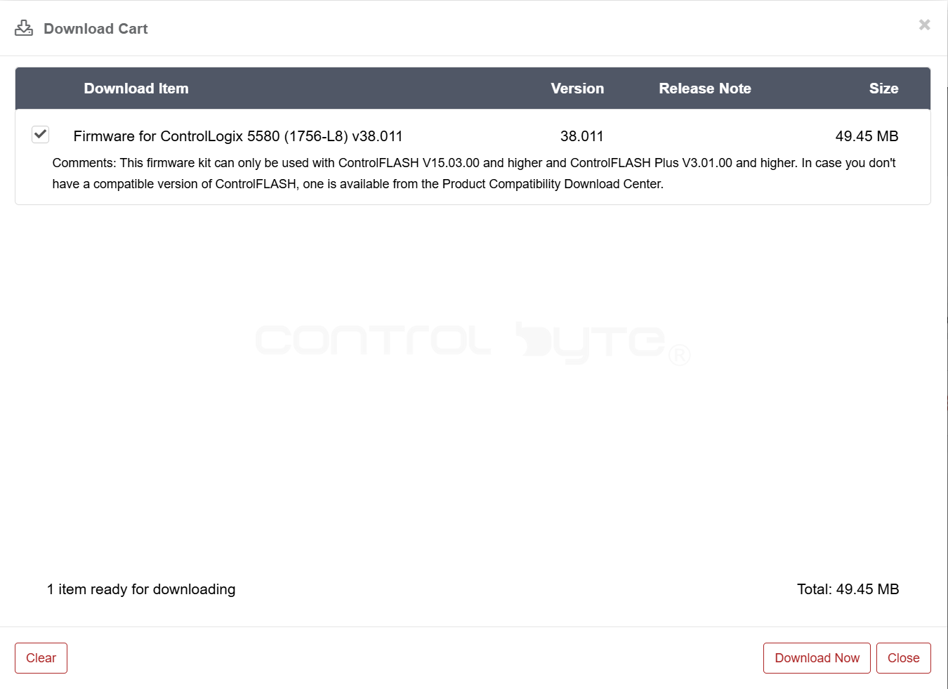
We confirm with the Download Now button.
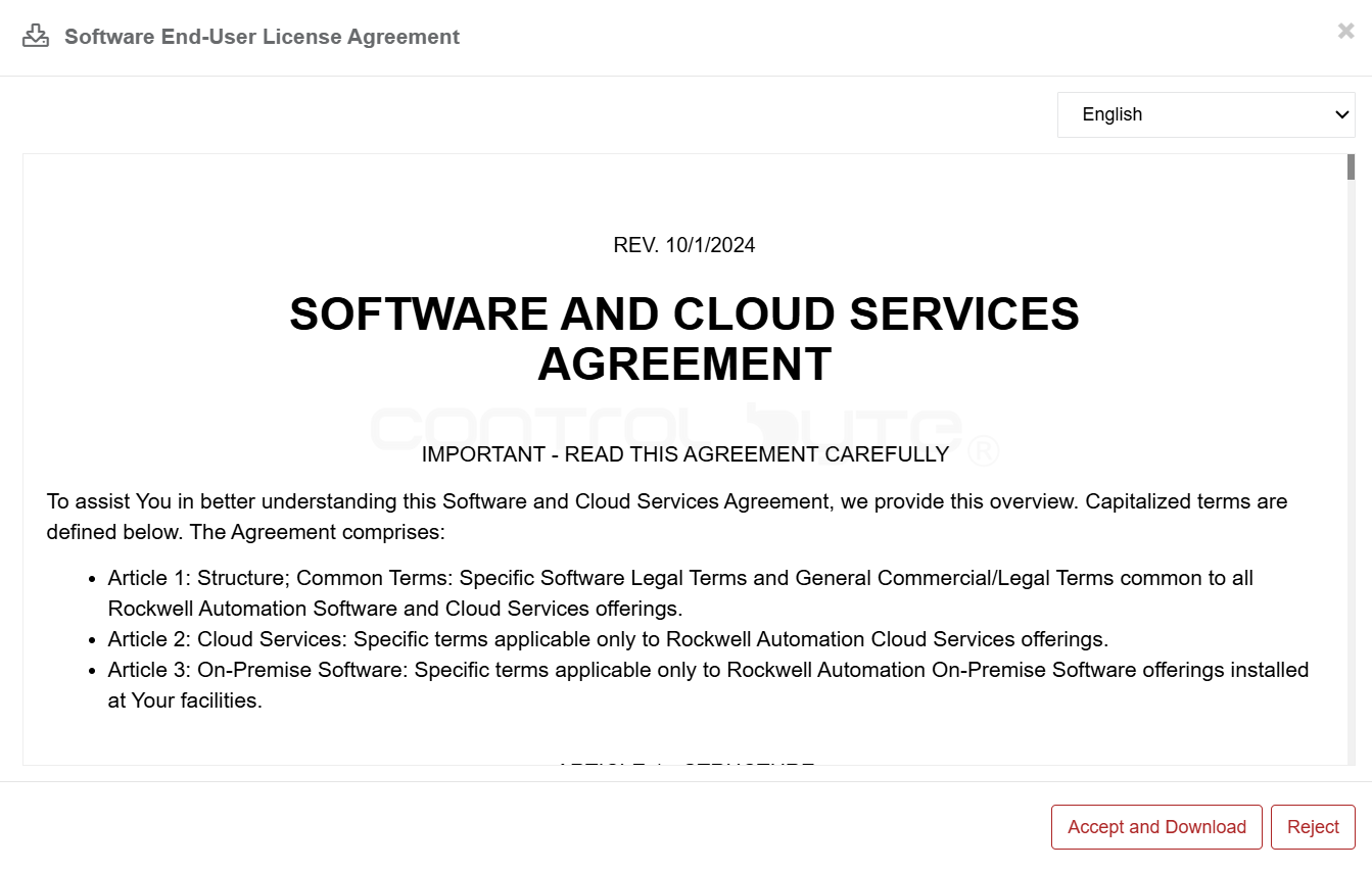
We accept the terms in order to download the file by clicking Accept and Download.
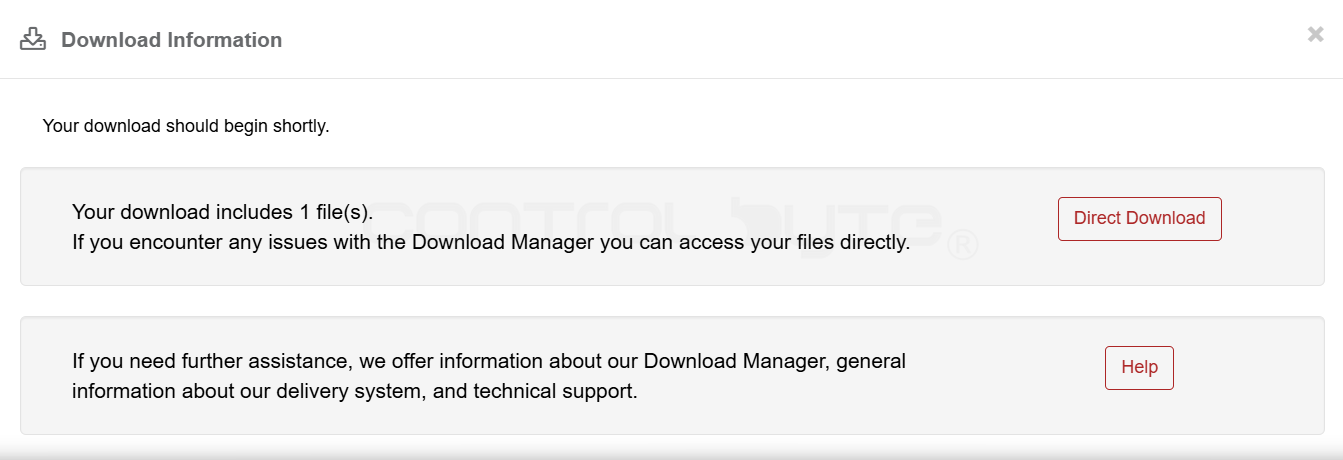
We have two download options to choose from: through the Download Manager, which downloads automatically to the Downloads folder, or downloading directly (Direct Download).
Communication - RSLinx Classic and FactoryTalk Linx
RSLinx Classic and FactoryTalk Linx (formerly RSLinx Enterprise) are communication servers that allow Rockwell software (e.g. RSLogix 5000 and Studio 5000 Logix Designer) to communicate with PLC hardware through various physical interfaces.
RSLinx Classic: The older, universal server. It is used mainly for programming controllers (downloading/uploading the program), network diagnostics, and communication with third-party software. It supports a very wide range of legacy networks (e.g.DH+,DeviceNet) and controllers (PLC-5, SLC 500).FactoryTalk Linx: A modern server optimized for visualization systems (SCADA/HMI) and large distributed applications. It is a native part of the FactoryTalk platform, offers higher process data throughput, and provides better support for controller redundancy.
To obtain RSLinx Classic and FactoryTalk Linx, you need to download the software installer from the Rockwell Download Center. Both programs can be downloaded separately or installed together during the installation of Studio 5000 Logix Designer.
Drivers in RSLinx Classic
EtherNet/IP Driver: The most commonly used driver; it automatically scans the local subnet and detects all available devicesEthernet devices: Requires manually entering the IP addresses of devices; used when the controller is in a different subnet or behind a router where auto-discovery does not work.RS-232 DF1 devices: Used for direct serial connections (via a COM port or a USB-to-Serial converter) to older controllers such as the SLC 500 or MicroLogix.Virtual Backplane(SoftLogix58xx, USB): Supports software emulators (SoftLogix) as well as direct connections through the built-in USB ports on modern ControlLogix/CompactLogix processors.- Hardware drivers (e.g.
1784-U2DHP,DeviceNet): Dedicated to specific physical converters and older-type industrial networks (e.g.Data Highway Plus).
Configuring the Ethernet Driver in RSLinx Classic
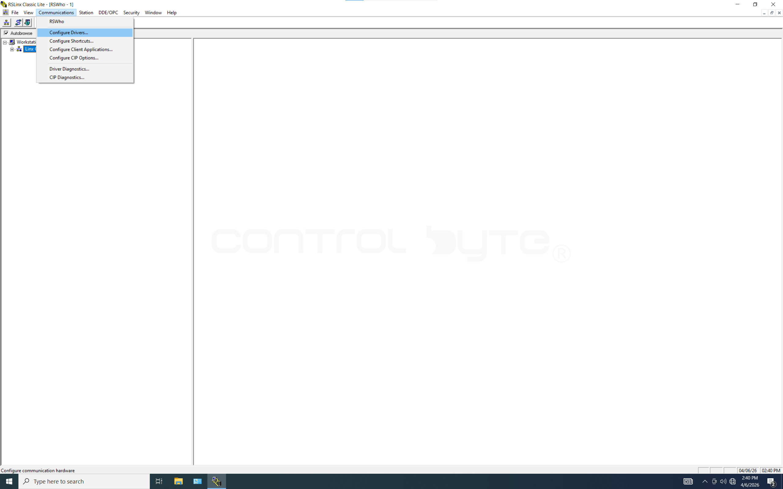
After launching RSLinx Classic, to establish a connection with the controller, click the Communications tab → Configure Drivers.
A small window will open in which we can choose from the available communication drivers.
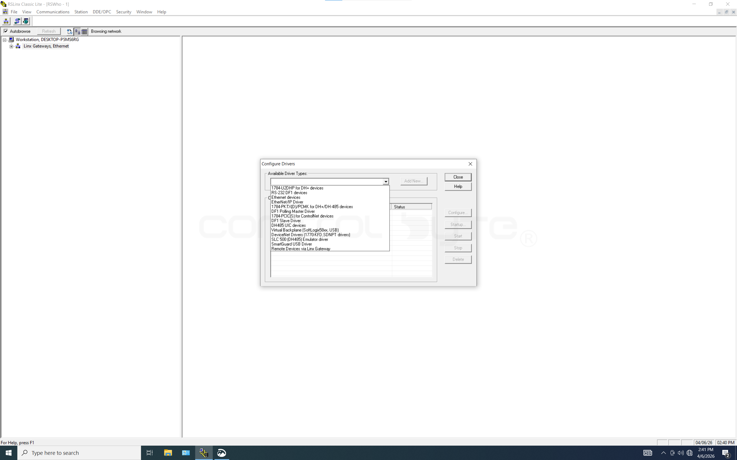
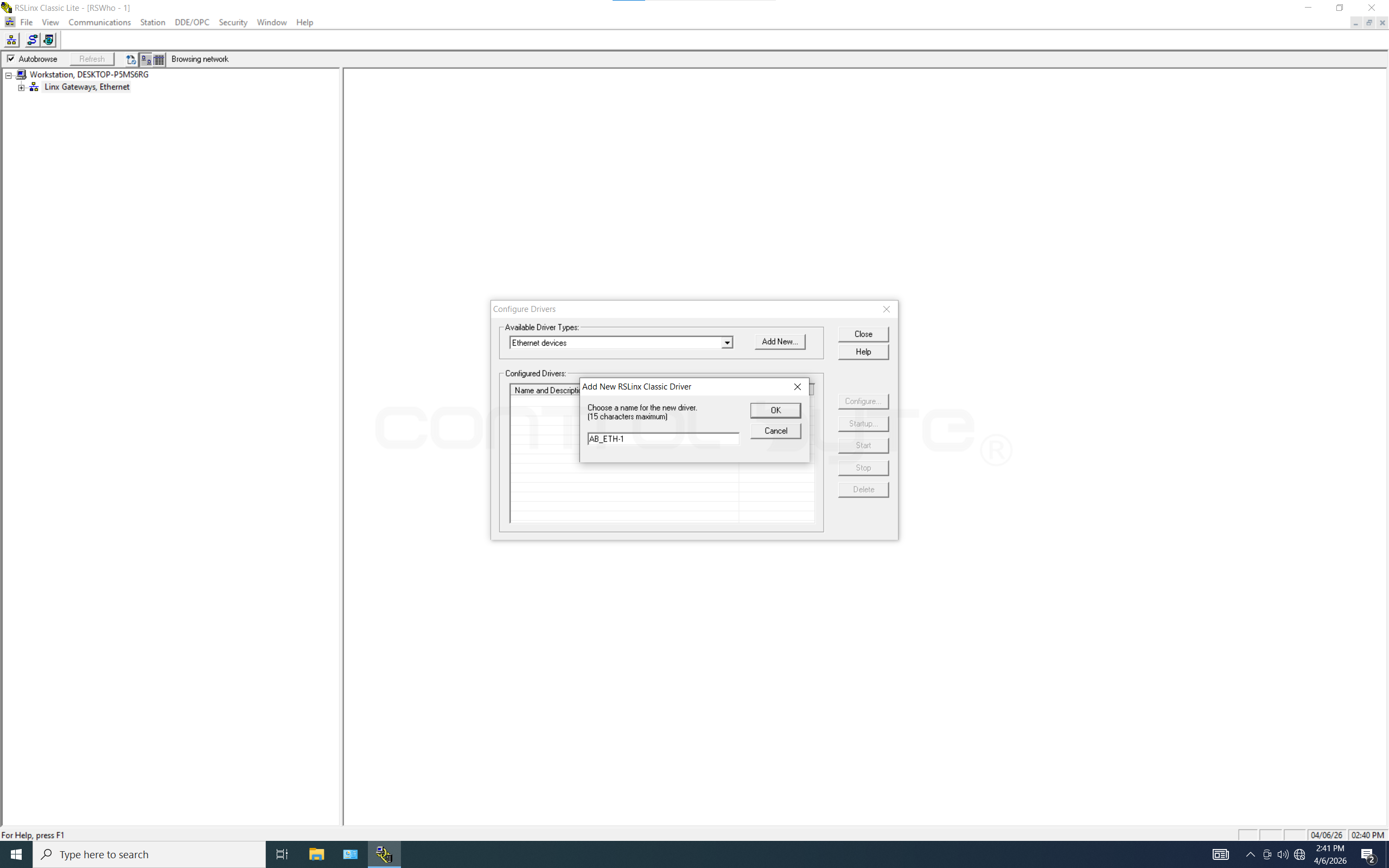
To select the Ethernet driver, we click it in the list and then add it with the Add New button, after which a window will appear for entering a name for the driver.
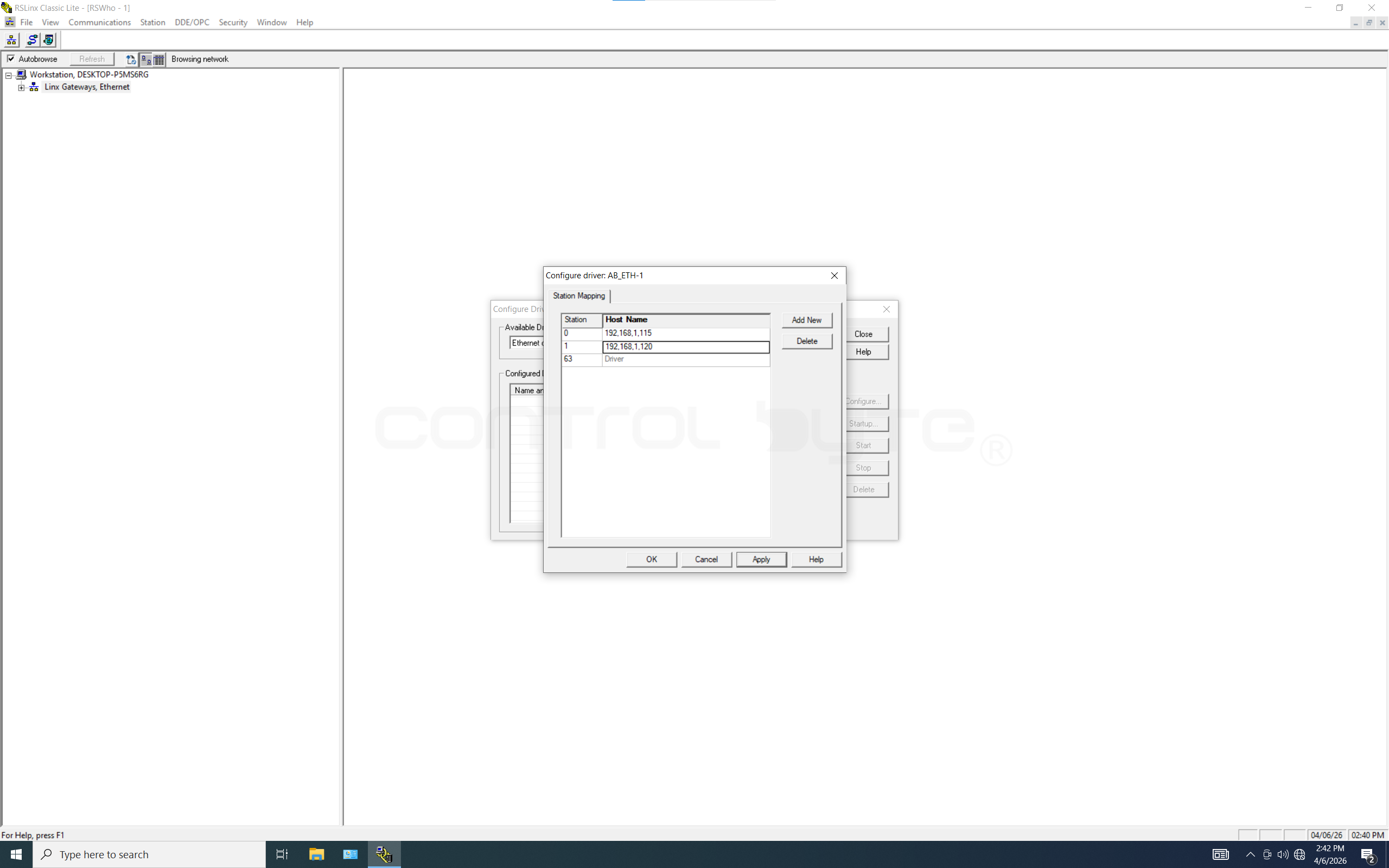
After choosing a name and clicking OK, the Configure Driver window will appear along with the Station Mapping tab, where we enter the IP addresses of the devices we want to connect to.
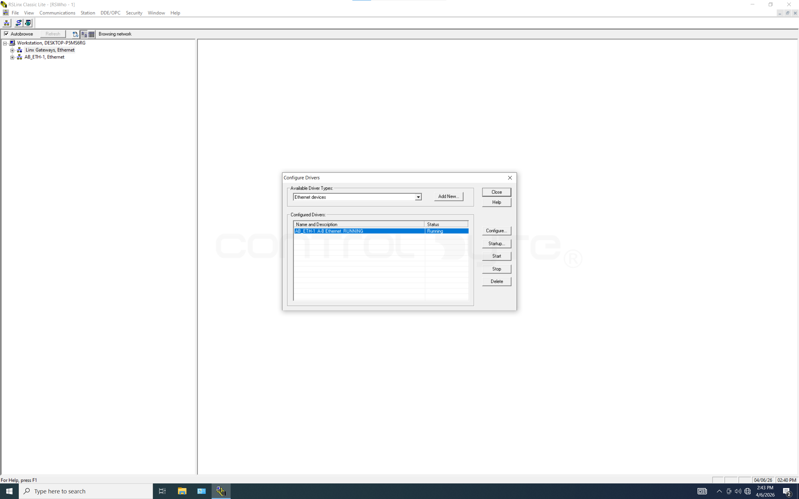
After filling in the list with the IP addresses we need, we click Apply and our driver will start, which is indicated by the RUNNING status.
Configuring the Ethernet Driver in RSLinx Classic
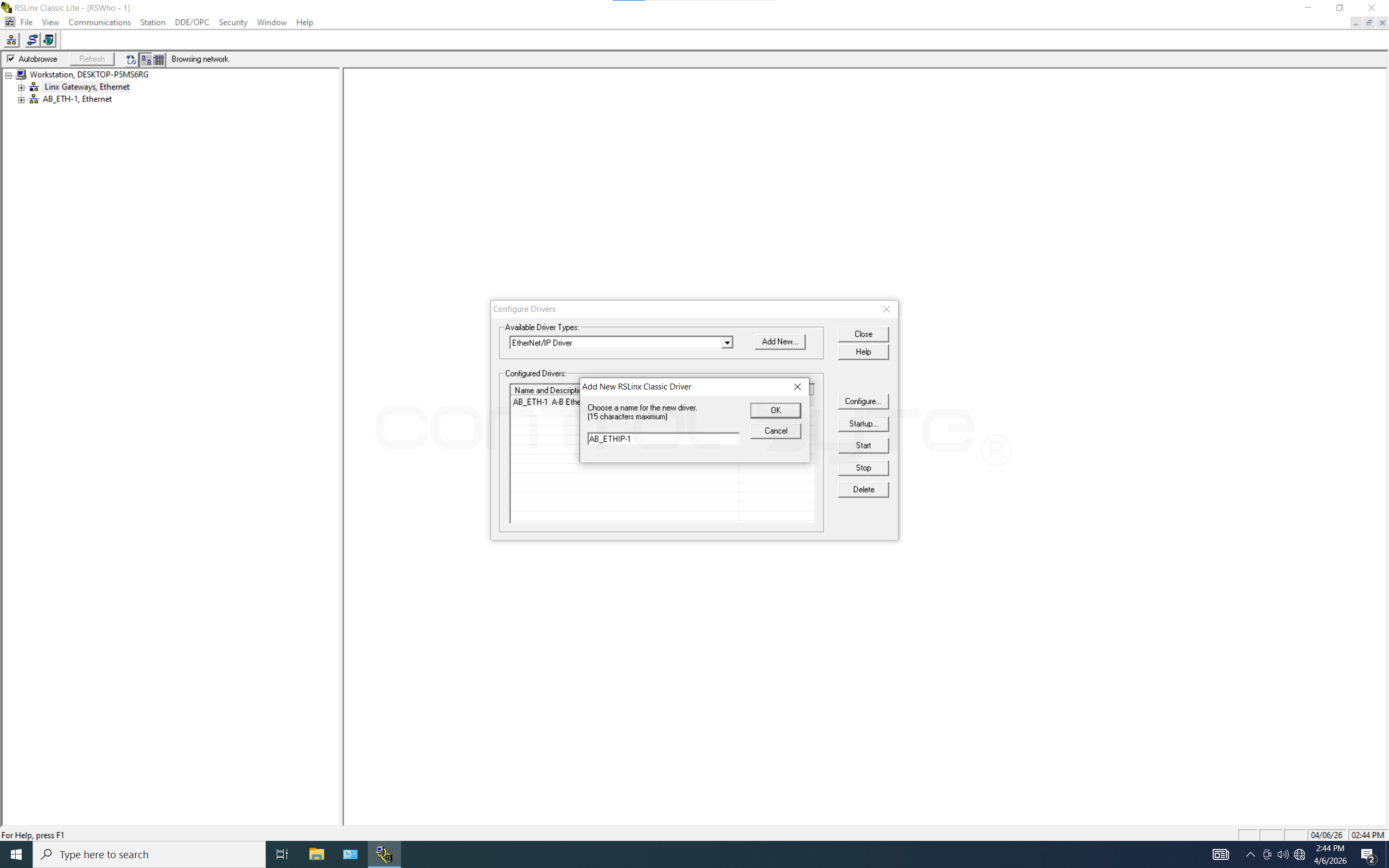
In the case of the Ethernet/IP driver, we add it the same way as the Ethernet driver and give it a name.
The difference is in the configuration: we do not enter IP addresses. We have two options to choose from, Browse Local Subnet and Browse Remote Subnet. Local Subnet is used to automatically search for controllers that are connected to exactly the same physical network as our computer/laptop. RSLinx sends a general query, and all nearby machines respond to it on their own and appear in the list. Every device on the same subnet receives this query. The network cards of computers or printers will ignore it, but the communication modules of PLC controllers will read the query and send RSLinx a reply with their parameters (IP address, device type, status). The "Remote Subnet" option allows RSLinx to send a query directed at a specific, remote subnet. We must manually enter the IP address of that subnet along with its mask.
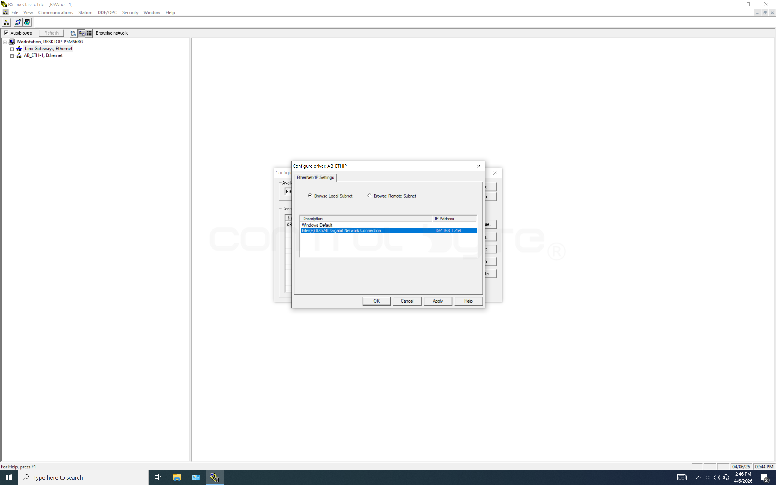
We check the status of our Ethernet/IP driver. Status RUNNING.

Configuring the Ethernet Driver in FactoryTalk Linx
FactoryTalk Linx has a more modern look than RSLinx Classic, but the procedure for adding drivers itself is the same. We click the plug symbol (Configure Drivers).
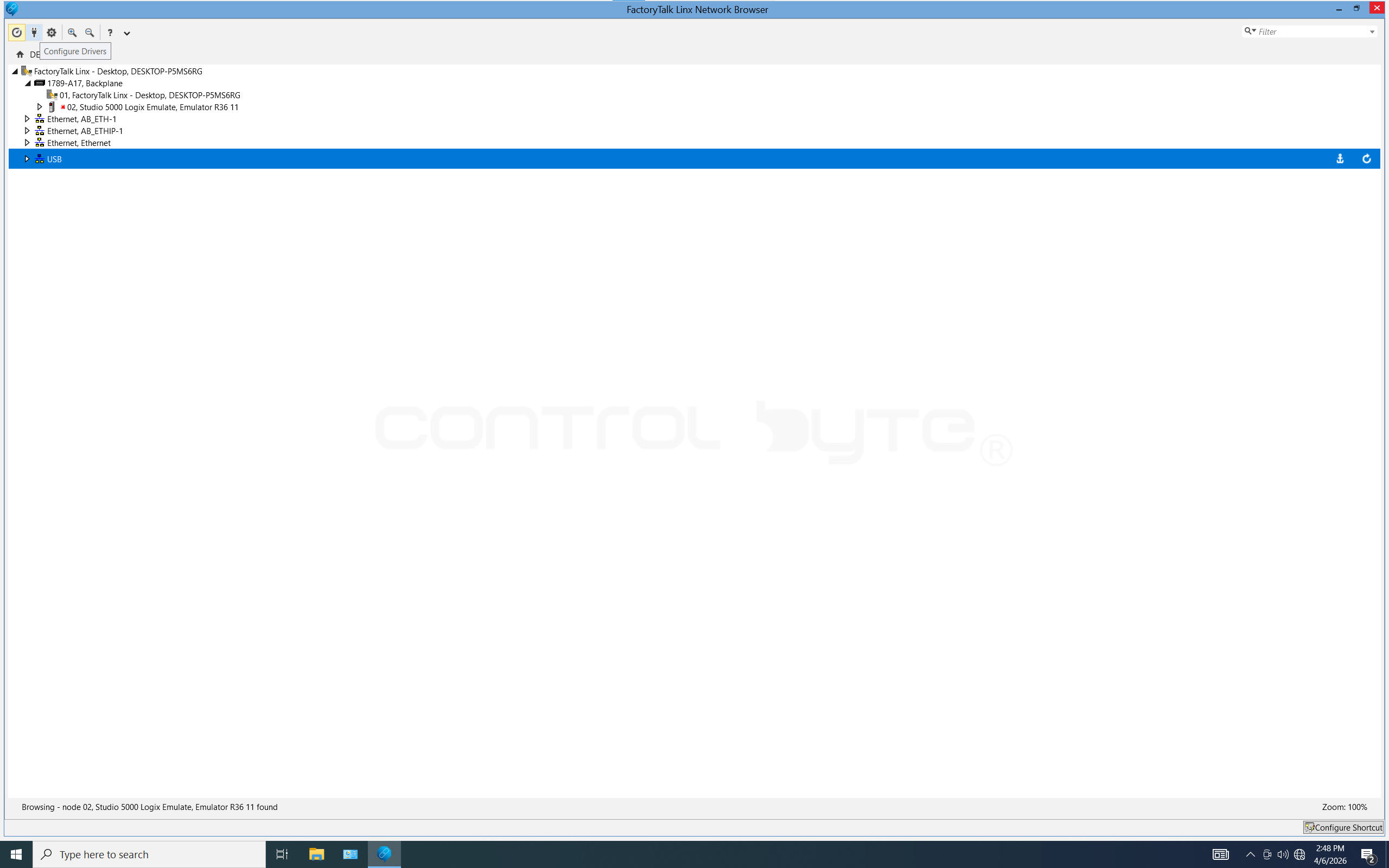
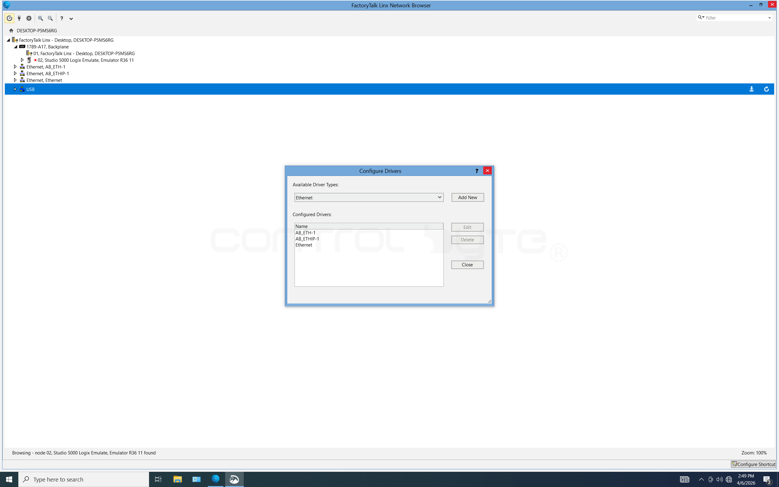
The Configure Drivers window will open. By default, after installation, FactoryTalk Linx created sample Ethernet and Ethernet/IP drivers. In addition, we also have a USB driver. To connect to the PLC we will use Studio 5000 Logix Emulate v36.
The Logix Designer Software
RSLogix 5000Logix Designer: The original engineering environment for the Logix5000 platform, supporting firmware versions fromv1tov20. It is used for hardware and network configuration and for writing logic (LAD,FBD,ST,SFC) for older ControlLogix and CompactLogix processors.Studio 5000 Logix Designer: The direct successor toRSLogix 5000, used for firmware versionv21and newer. It is the main tool for programming modern controllers, integrating control logic, drive configuration (Motion), and safety modules (Safety) within a single project.Studio 5000 Logix Emulate: A software emulator that creates a virtual controller in the computer's memory. It lets you run and fully test code written inLogix Designerwithout owning a physical processor, enabling signal simulation and communication with HMI panels.FactoryTalk Logix Echo: The successor toStudio 5000 Logix Emulate. Modern software from Rockwell Automation used to emulate the latest PLC controllers from the ControlLogix 5580 and CompactLogix 5380 families. Its biggest advantage is that it lets you run, test, and debug a program directly from Studio 5000 in a virtual environment, without having to make absolutely any modifications to the code or the hardware configuration of the project.
Configuring Studio 5000 Logix Emulate
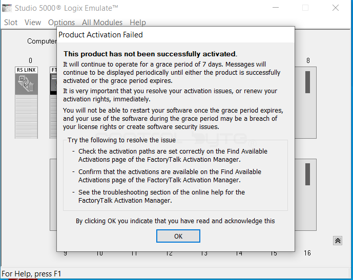
After launching Studio 5000 Logix Emulate, we receive a notice that it will be available for only 7 days. After that period it cannot be used without an appropriate license.
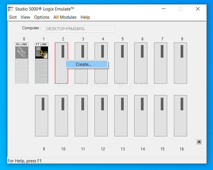
To create a virtual PLC controller, we click for example slot 2 and, with a right-click, select the Create option.
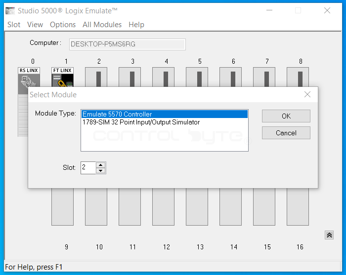
The Select Module window will appear. We choose the Emulate 5570 Controller option.
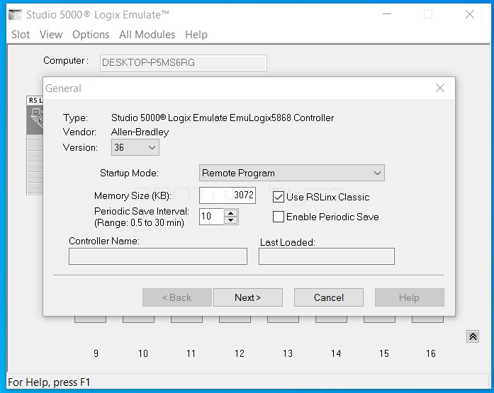
After selecting the module, the General window will appear. We leave all the options exactly as they are set in the image.
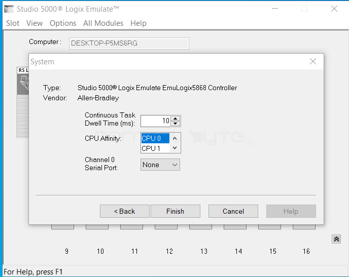
In the System window we also change nothing and simply leave the defaults.
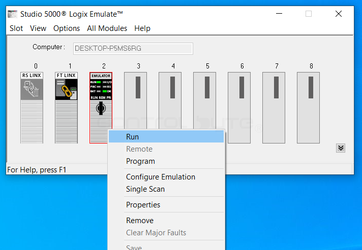
After creating the controller, we right-click and select the Run option to put the controller into Run mode and check that there are no errors.
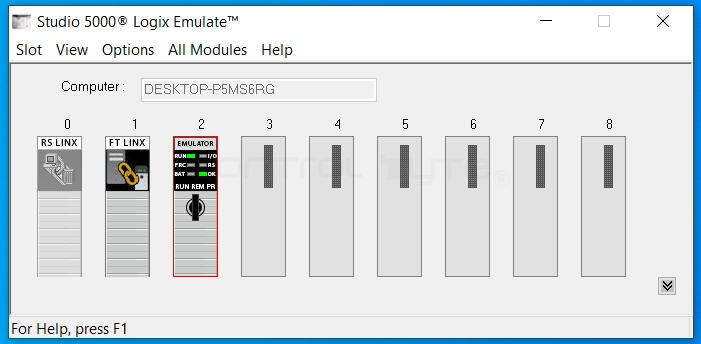
The controller is in RUN mode and there are no errors. It is ready for the program to be downloaded and for simulation.
Programming Languages in Studio 5000 Logix Designer
In Studio 5000, logic can be created using the following programming languages: Ladder Diagram (LD) - the Ladder Diagram is the most commonly used language, which in appearance resembles electrical schematics. It consists of contacts and coils, which makes it extremely readable for electricians and maintenance staff. It is ideal for logic (bit-level) control and simple function blocks.
Function Block Diagram (FBD) - the Function Block Diagram is a graphical language based on connecting ready-made blocks with lines that carry data. It is very clear when building control loops (e.g. PID) and processing analog signals. It makes it easy to trace the flow of values between individual functions.
Structured Text (ST) - Structured Text is a high-level text language that resembles programming in Pascal or C. It is indispensable for performing complex mathematical calculations, operations on large data sets, and for creating loops and logical conditions. It allows very compact representation of complex algorithms.
Sequential Function Chart (SFC) - the Sequential Function Chart is a language used for programming the sequences and stages of a machine's operation. It divides the program into specific Steps and Transitions, which allows the entire technological process to be represented graphically. It is excellent for managing machine operating modes and Batch-type processes.
Configuring a Sample Project in Studio 5000 Logix Designer
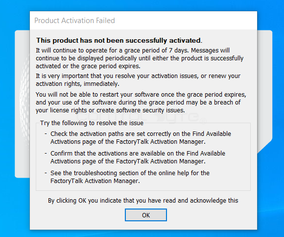
After launching Studio 5000 Logix Designer, we receive a notice about the 7-day usage period of the program, just as with the Emulator.
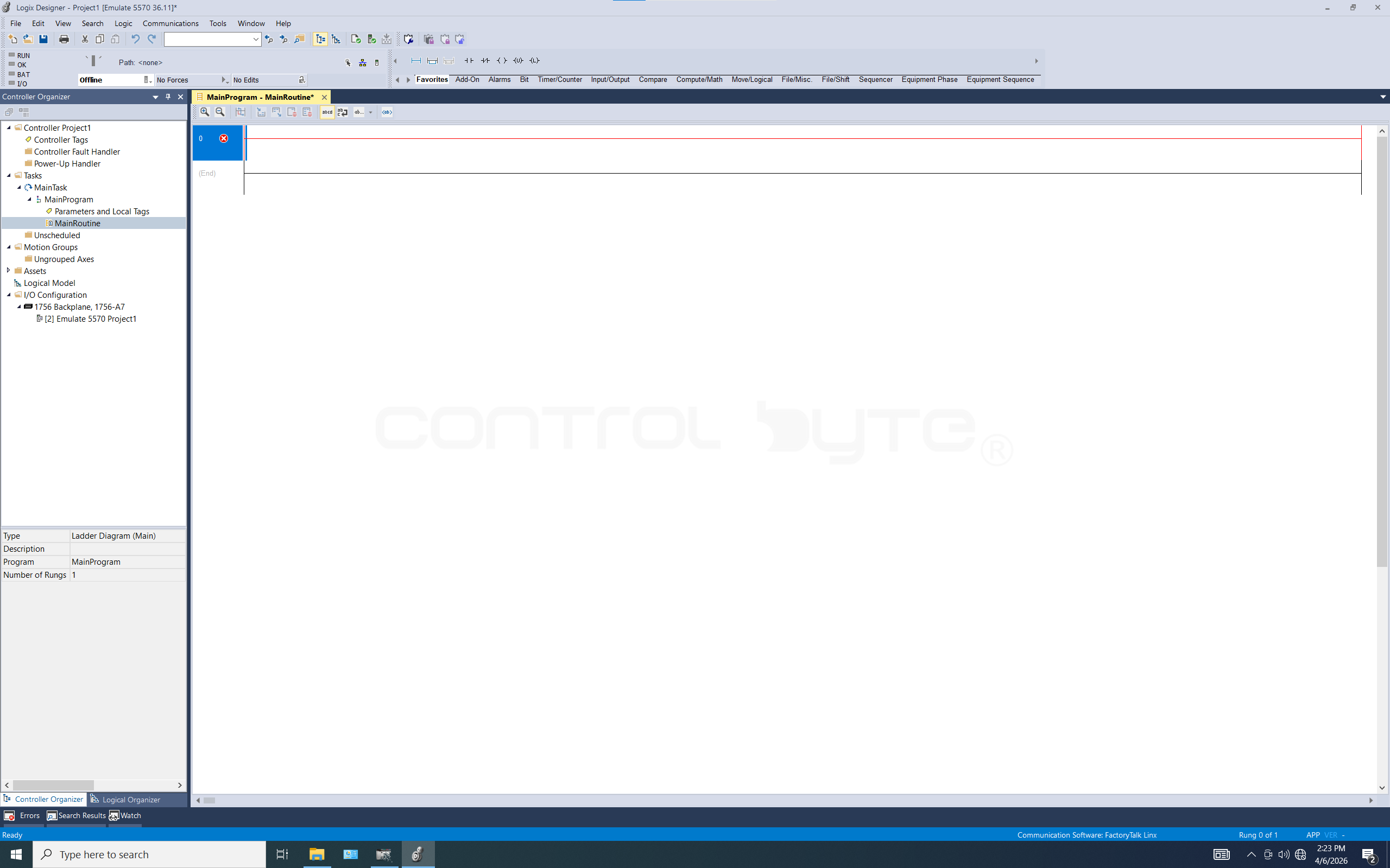
After opening our project, we can move on to writing our first program. To do this, in the Controler Organizer tab, in the Tasks folder → MainTask → MainProgram (we expand it) and open MainRoutine.

At the moment, there is no logic in MainRoutine yet. The program logic will be written in ladder logic (Ladder Logic).
How to Read Ladder Logic?
Reading ladder logic (Ladder Diagram) resembles analyzing an electrical schematic, where current flows from the left vertical rail to the right one. The program is analyzed from top to bottom and from left to right, line by line (the so-called rungs).
- Contact logic: On the left side of the rung are the conditions (contacts). A normally open contact (--| |--) "conducts" when its assigned signal is active (has a value of 1), and a normally closed contact (--|/|--) conducts when the signal is inactive (has a value of 0).
- Result of the operation: On the right side of the rung is the coil (--( )--), which represents the result or the execution of an action (e.g. energizing a physical output or setting a variable in memory).
- Path continuity: For the coil on the right side to be activated, an uninterrupted conducting "path" must form from the left rail through all of the satisfied conditions (contacts).
What Are Variables?
Variables (called Tags in Studio 5000) are "digital drawers" in the controller's memory in which specific information is stored. Each variable has its own unique name and a type that determines what data it can hold (e.g. only 0 or 1, an integer, or text).
- Symbolic addressing: Instead of working with physical input/output numbers, you give variables human-readable names, e.g.
Start_Przenosnikainstead ofLocal:1:I.Data.0. This way the program reads like an instruction rather than a string of digits. - Data types: Variables are divided into simple ones (e.g.
BOOLfor on/off states,REALfor floating-point numbers) and complex ones (e.g.TIMER, which stores the preset time and the current elapsed time). - Scope: Variables can be
Controller Tags(visible throughout the entire program) orProgram Tags(accessible only within a specific program block). This helps keep things organized and avoids accidentally overwriting data in another part of the machine. - State memory: A variable remembers the result of an operation from a ladder rung and lets it be used elsewhere in the program, serving as a link between different controller functions.
To create variables, open Controller Tags in the Controller Project1 folder.
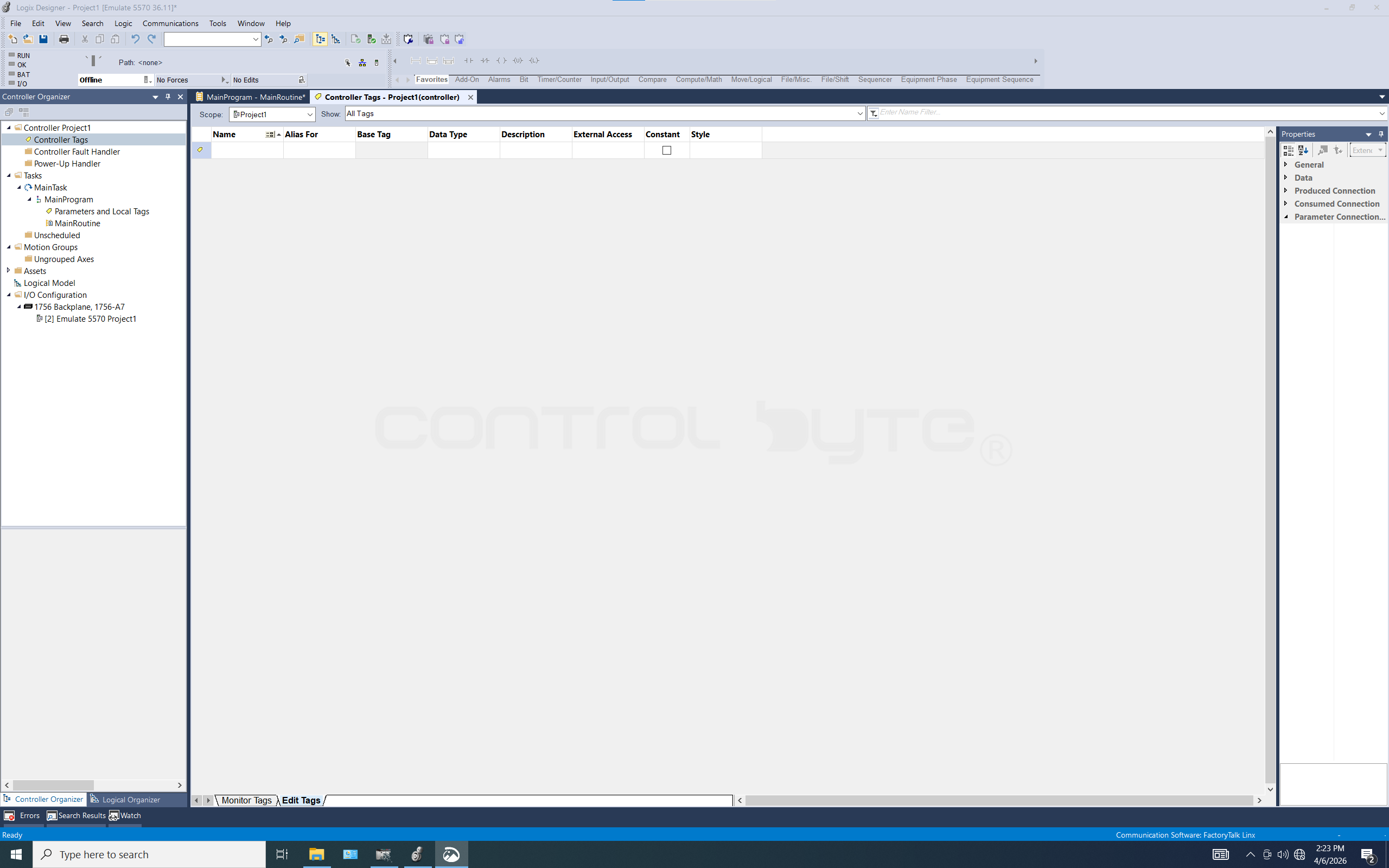
In our program we will need three variables: Start, Stop, and Motor. We create a variable by entering its name in the Name field and its type in the Data Type field.
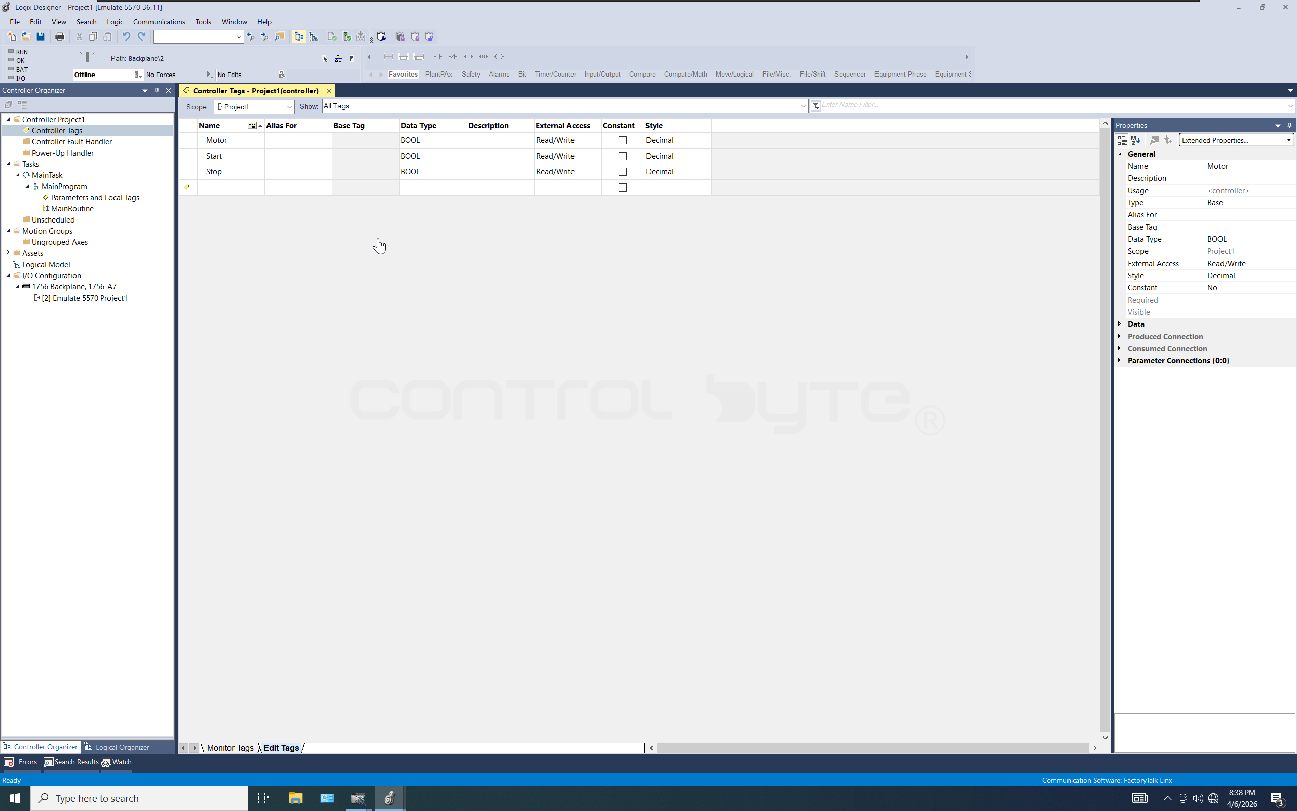
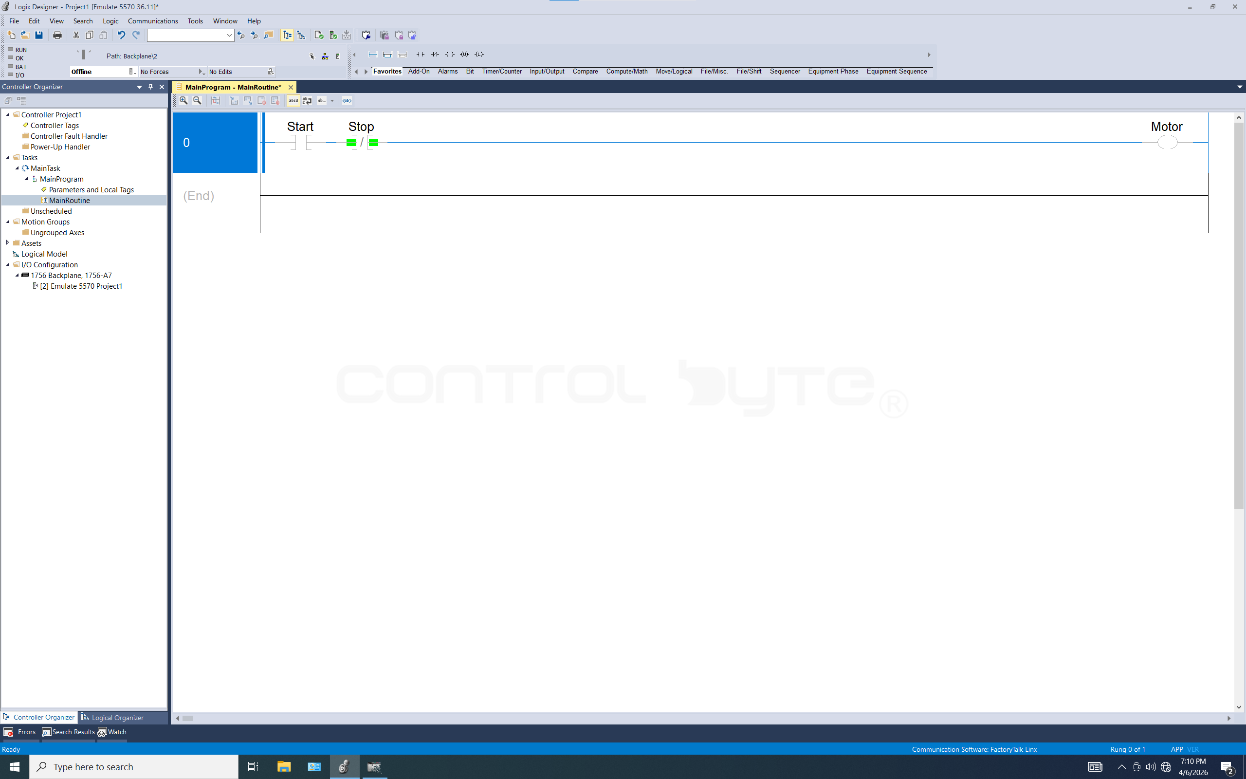
After creating the variables, we return to MainRoutine. Our first program will be simple. The START button will start the MOTOR, and the STOP button will stop it. START button - normally open contact (--| |--) input. STOP button - normally closed contact (--|/|--) input. MOTOR - coil (--( )--) output.
To add elements such as contacts and coils, we can do so using the ladder logic elements in Studio 5000 (Ladder Common Logic). These elements can be enabled by clicking the View -> Toolbars tab.
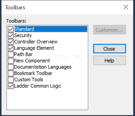

After selecting the Ladder Common Logic option, the elements will appear at the very bottom of the navigation bar (below the area labeled Offline; they can also be moved if someone does not like them in that spot). There is also the option of using the elements without the Ladder Common Logic option. On the right side of the navigation bar we have the Favourites field, where we will find the elements we are interested in.
After inserting an instruction into the rung, the previously created variables need to be assigned. The variable name is suggested by the program; we press the Enter key and the variable is assigned to the instruction.
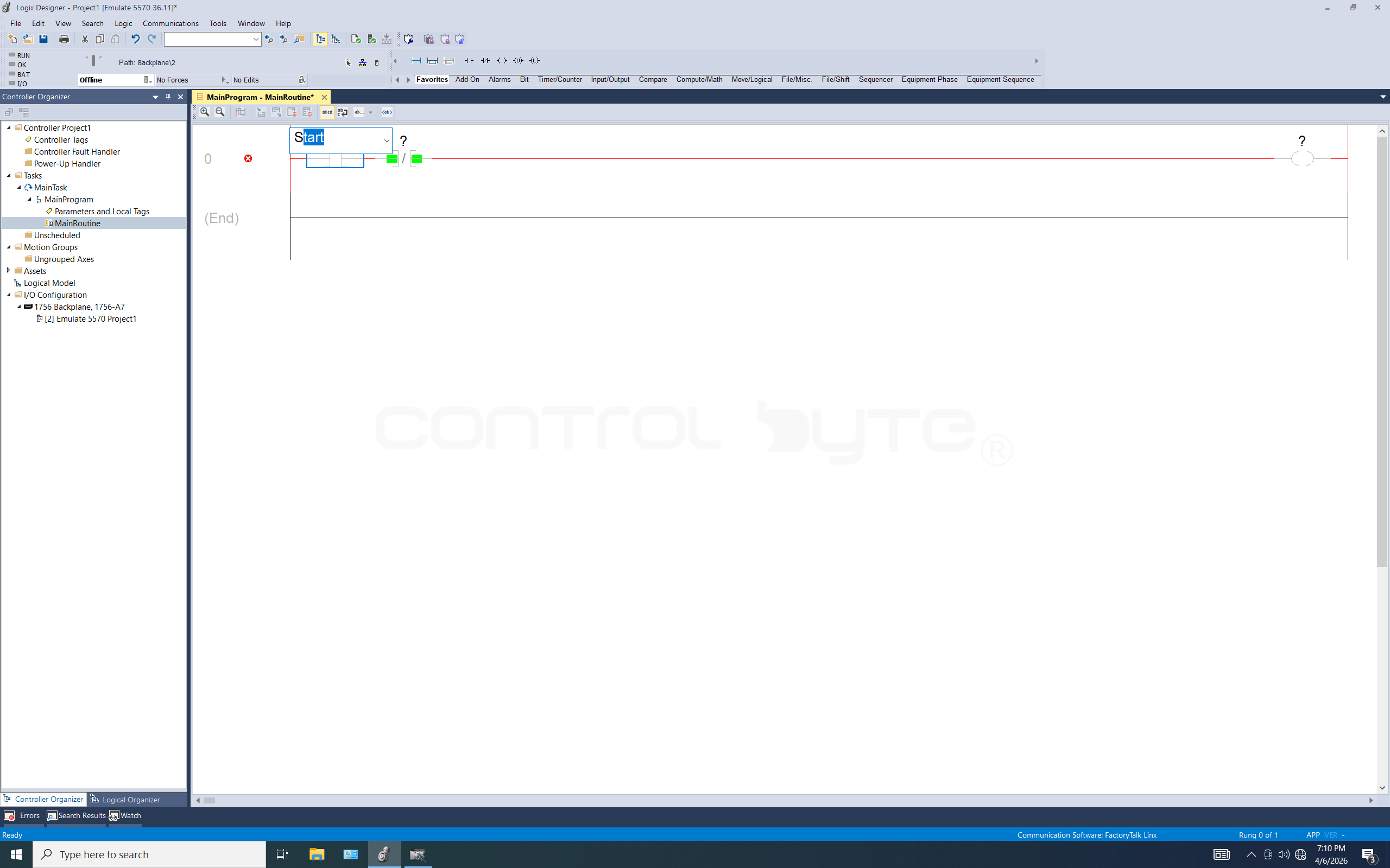
The program should look like the image below.
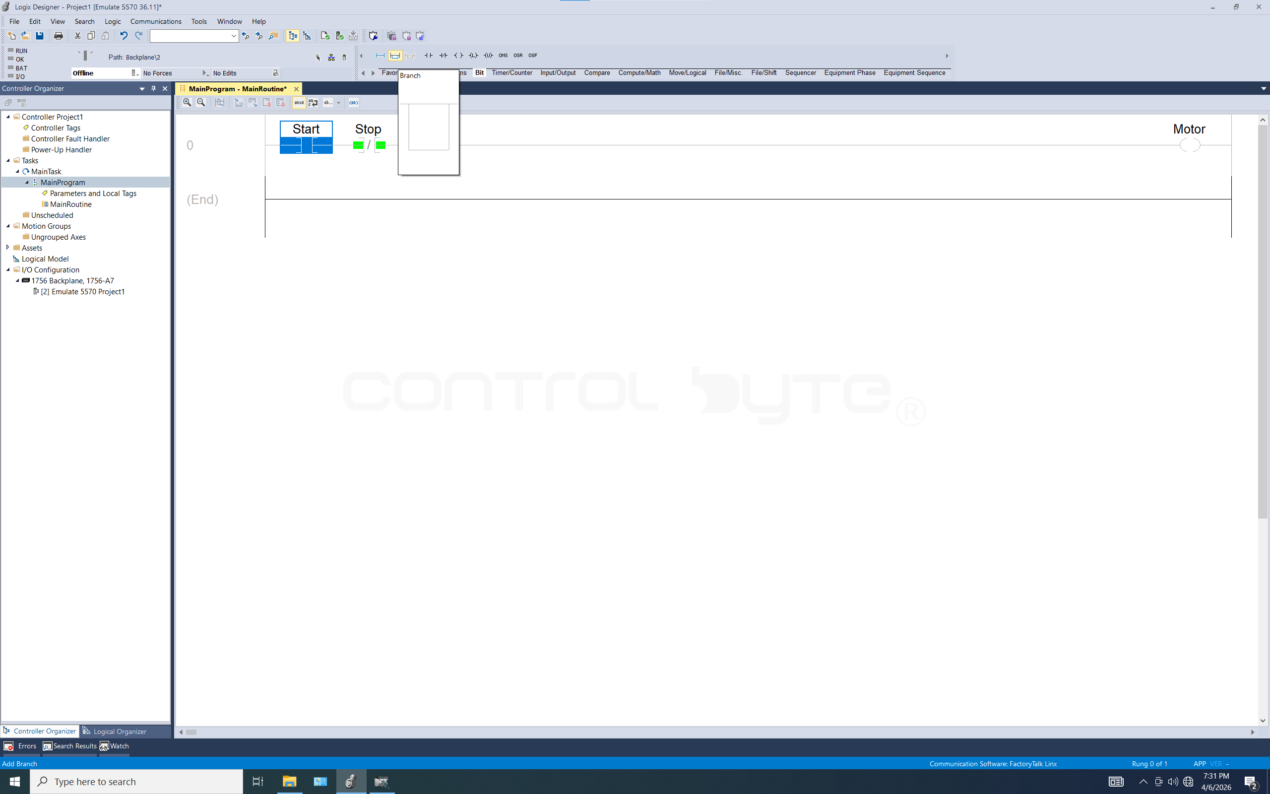
The next step is to add a seal-in from the Motor signal, meaning that after the Start button is pressed and released, the motor will continue running. We can achieve this by adding a parallel connection (Branch).

The seal-in has been implemented. We save the project with the Ctrl + S key combination or by clicking the diskette icon under the Edit tab. Now the finished program can be downloaded to the processor that was configured earlier in Logix Emulate. The operation of loading the program into the controller is Download. The operation of retrieving the program from the controller is Upload.
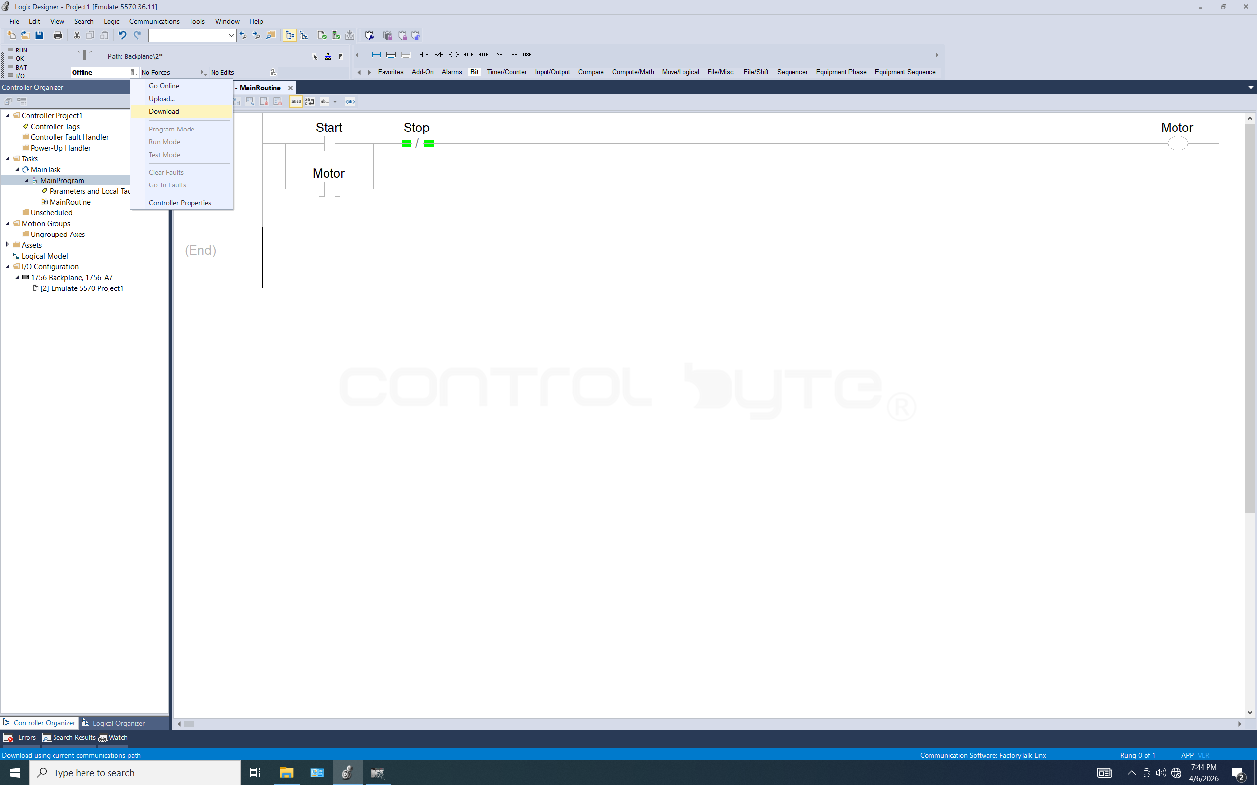
To perform a download, we click the controller's Offline field and select the Download option.
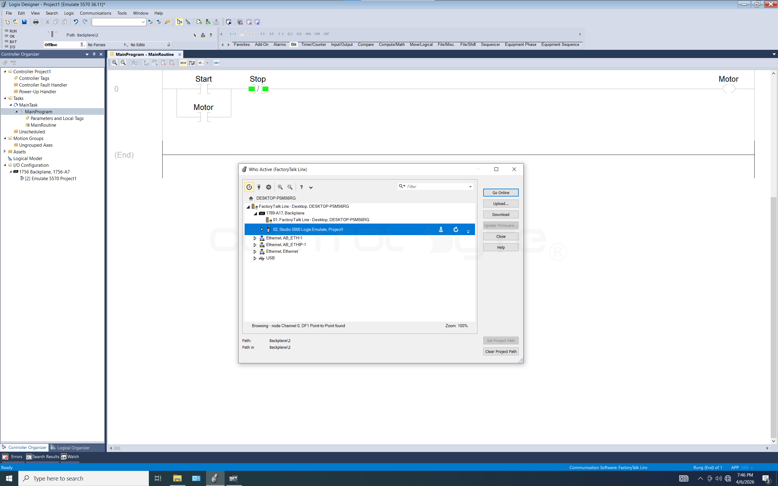
The first time the program is downloaded to the PLC, the Who Active window will open (it is a small version of FactoryTalk Linx). We must point to the path of the simulating processor and can then save it by clicking Set Project Path. Then we click the Download option.
We will be asked whether we are sure we want to reload the controller. We click the Download button again.
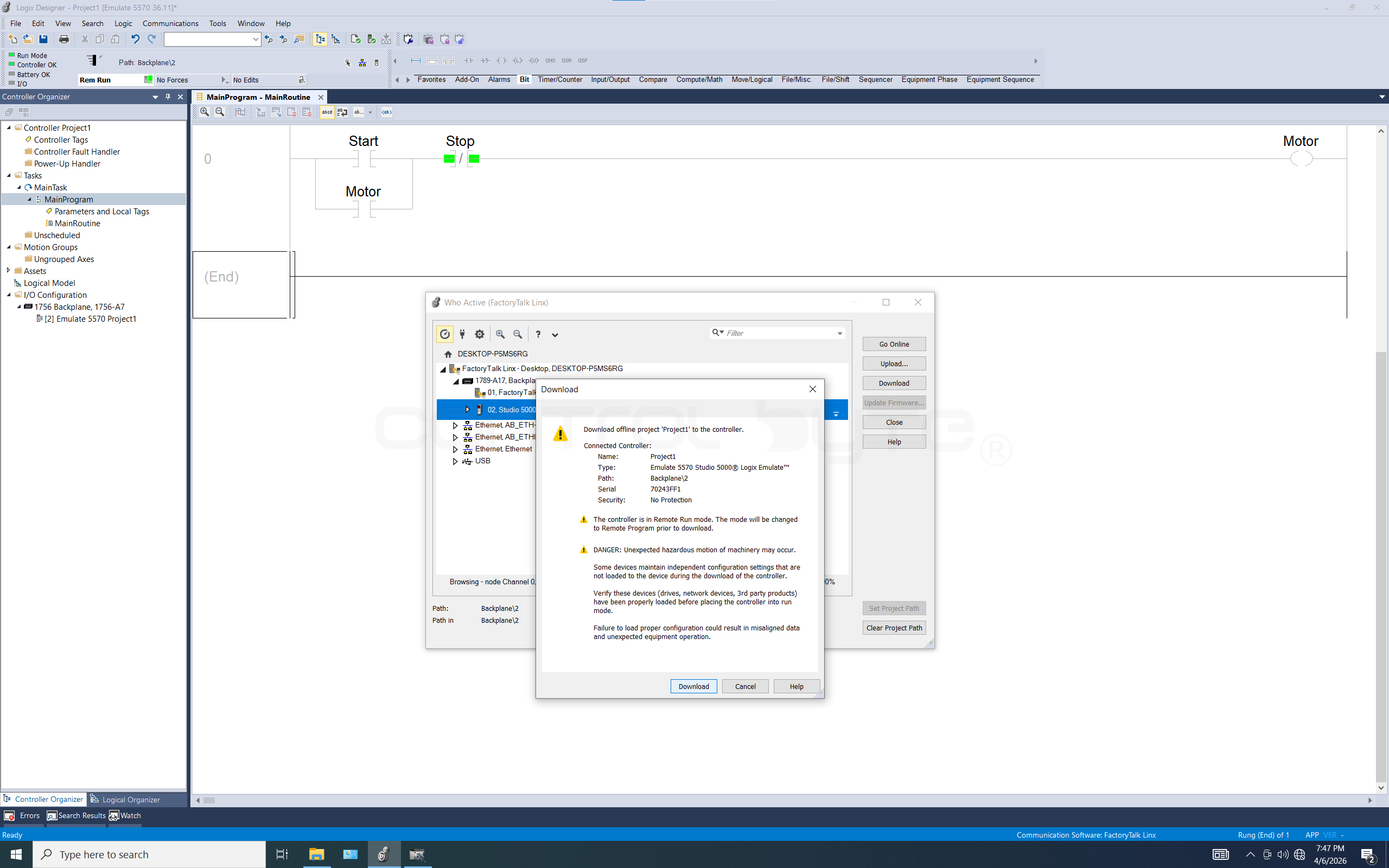
The process of downloading the program to the PLC is in progress.

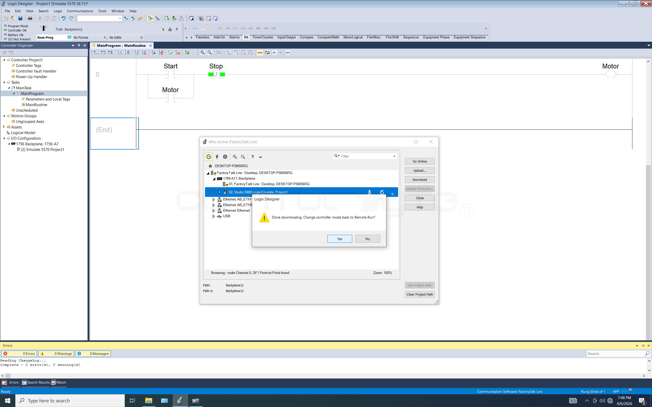
After the program has been successfully downloaded to the controller, we will be asked whether we want to change the controller mode to Remote Run. We choose Yes.
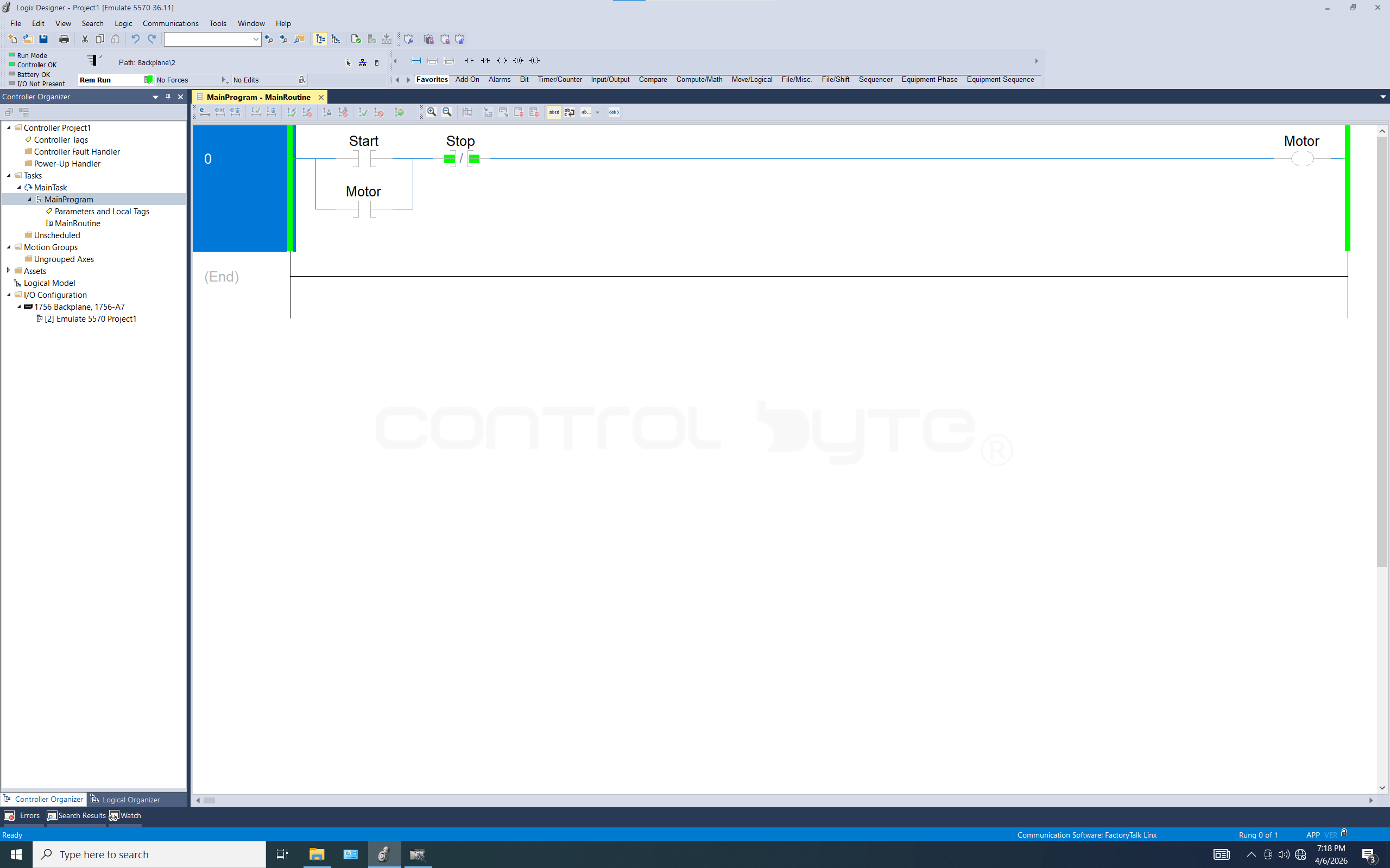
The controller is now in Online mode (this is shown by the RemRun label in the place where the Offline label was previously). The program is running; we can simulate and check the states of our variables.
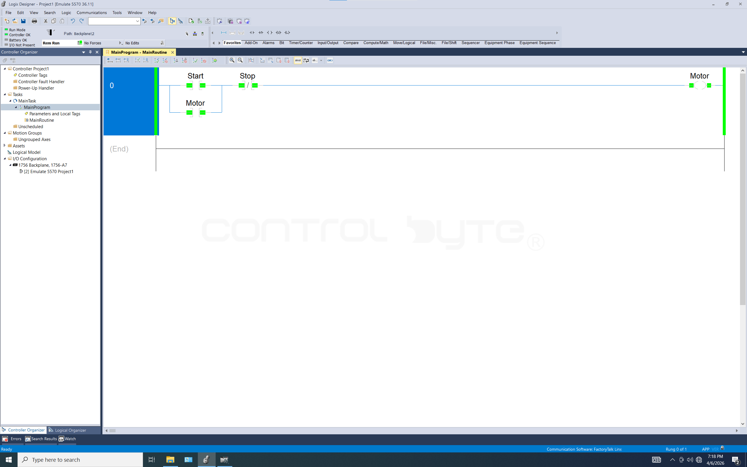
By right-clicking on a variable, you can change its state with the Toggle command, or by left-clicking and using the Ctrl + T keys. At the end of this post I will also describe the individual operating modes of the controller.
Controller Operating Modes
Run- The controller executes the program, refreshes the inputs/outputs, and handles communication. In this mode (if the switch is in the RUN position) you cannot edit the program online or change the hardware configuration.- Program - The controller's outputs are forced into a safe state (usually off), and the logic process is stopped. This mode is used for downloading the entire project (
Download) or making major changes to the configuration. Remote Run- The physical switch is in the middle position (REM), which allows the mode (Run/Program) to be changed remotely from the computer. It also enables editing the program online without stopping the machine.Test Mode- Available in Remote mode, the controller executes the logic but does not activate the physical outputs. Ideal for checking new fragments of code.Fault- A fault state (red OK LED) in which the processor stops operating due to a critical error.
Summary
You now have Studio 5000 installed, communication configured, and your first working program in ladder logic. In the next post we will dive into Boolean logic and logic gates in Studio 5000 Logix Designer.
Next in the series
Boolean logic in Studio 5000: AND, OR and NOT gates
Build AND, OR, NOT, NOR and NAND gates in ladder logic with XIC, XIO and OTE.
Previous in the series
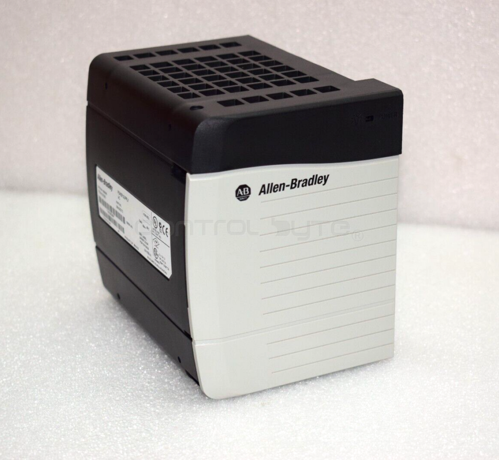
Allen-Bradley Controllers: CompactLogix, ControlLogix, Micro800
Get to know the Allen-Bradley portfolio: Micro800, CompactLogix and ControlLogix 1756.
Author