PLC system variables are one of those features that separate a beginner from a programmer who can actually diagnose a machine. In Connected Components Workbench (CCW) they expose the controller's status and control - scan time, scan counter, fault state, the first scan pulse - as ordinary global variables you can read straight from your logic, with no extra code. In this lesson we look at the most useful ones on an Allen-Bradley Micro850 and then put the First Scan bit to work in a real exercise, so a rung starts itself the moment the controller enters RUN.
What PLC system variables are
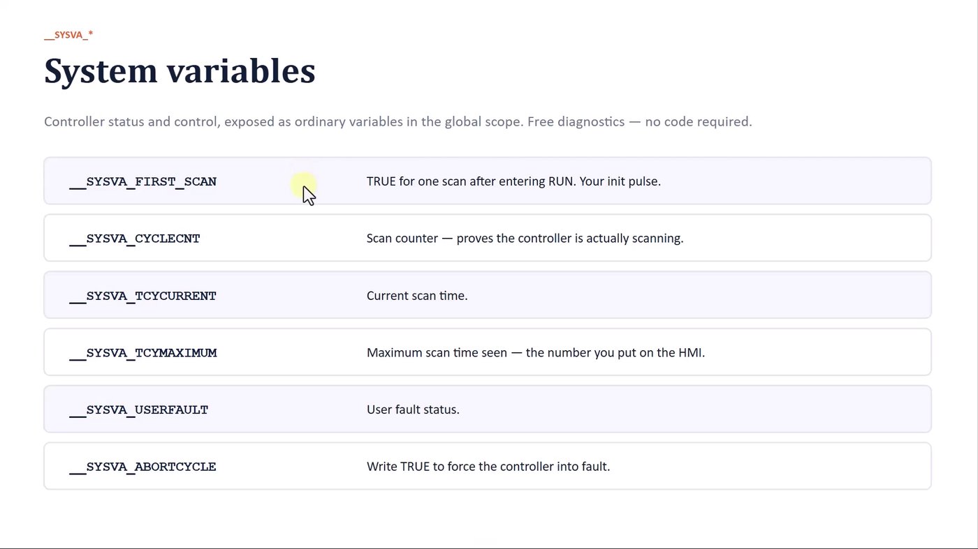
System variables are read (and in a few cases written) exactly like any other tag in the global scope. They give you free, built-in diagnostics. These are the ones worth knowing from day one:
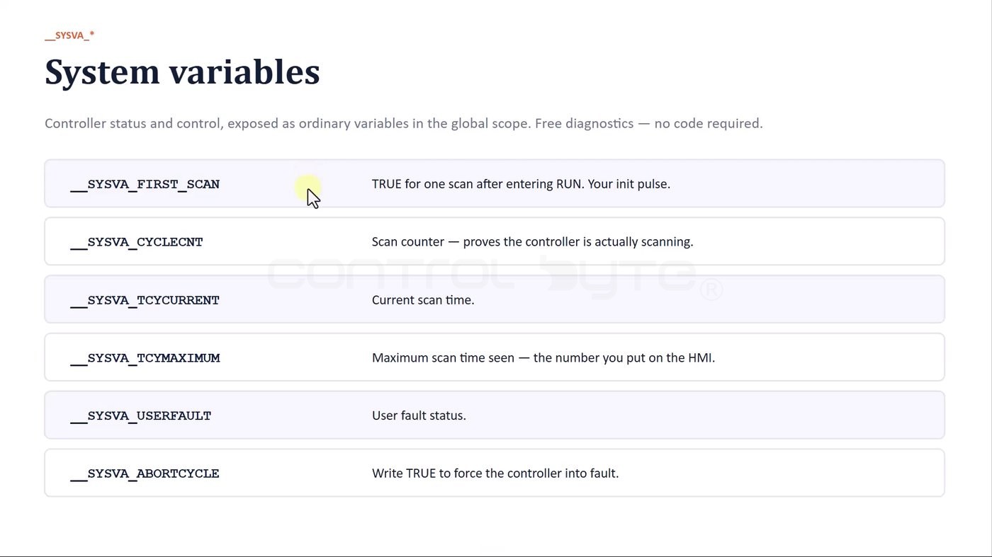
__SYSVA_FIRST_SCAN- TRUE for exactly one scan after the controller enters RUN. This is your initialization pulse.__SYSVA_CYCLECNT- the scan counter; if it keeps incrementing, the controller is really scanning.__SYSVA_TCYCURRENT- the current scan (cycle) time.__SYSVA_TCYMAXIMUM- the maximum scan time seen so far, the number you typically expose on an HMI.__SYSVA_USERFAULT- the user fault status.__SYSVA_ABORT_CYCLE- write TRUE to force the controller into fault, for example when your program detects an exception it cannot recover from.
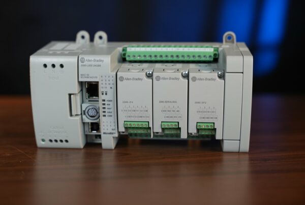
If you are new to this controller family, it helps to first understand the hardware it runs on - see our guide to the Allen-Bradley Micro850 2080-L50E build and capabilities.
The exercise: a latching circuit in CCW
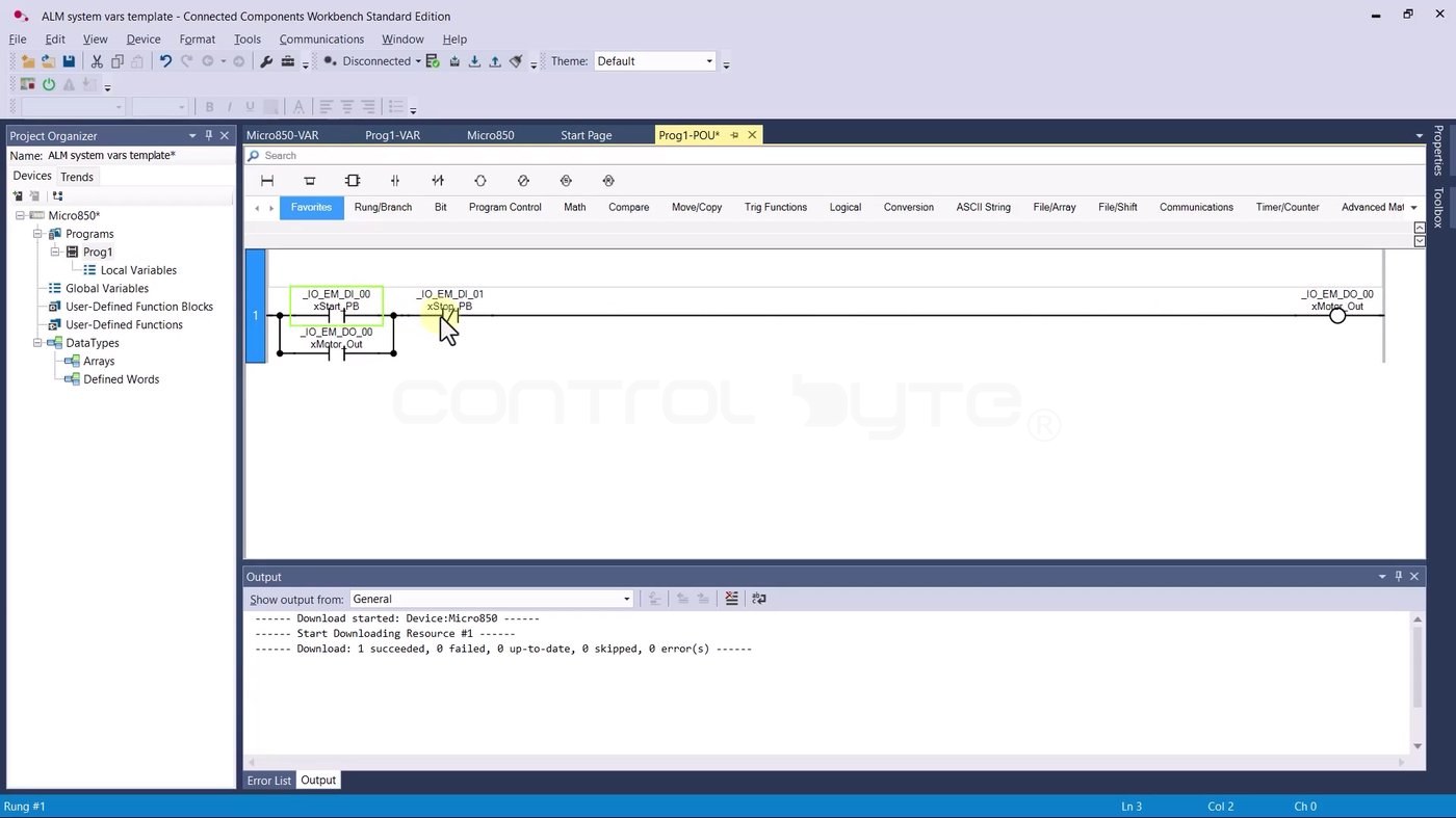
We start from a project template with a simple latching (seal-in) circuit in program PROG1. It references the physical inputs - the start button _IO_EM_DI_00, the stop button _IO_EM_DI_01 - and drives the output _IO_EM_DO_00. This is the classic motor start/stop rung.
Testing the circuit in the simulator
You do not need physical hardware to try this. Download the program to the built-in Micro800 Simulator (the PLCSIM tab, or the toolbar shortcut). Confirm the download, switch the simulator to RUN mode, and CCW jumps into the online monitoring view.
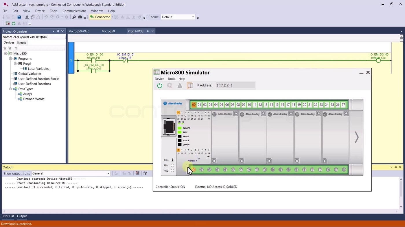
Click the first input - input 00, the start button - and the first output turns on and the circuit latches. Press stop and it drops out. So far, nothing surprising: to energize the output after entering RUN, you have to press start.
Viewing system variables live
Now open Global Variables and scroll down to the system tags. They refresh in real time. Here you can watch the scan counter climb, read the current cycle time (__SYSVA_TCYCURRENT, about 280 ms in this project), and see the state of __SYSVA_FIRST_SCAN.
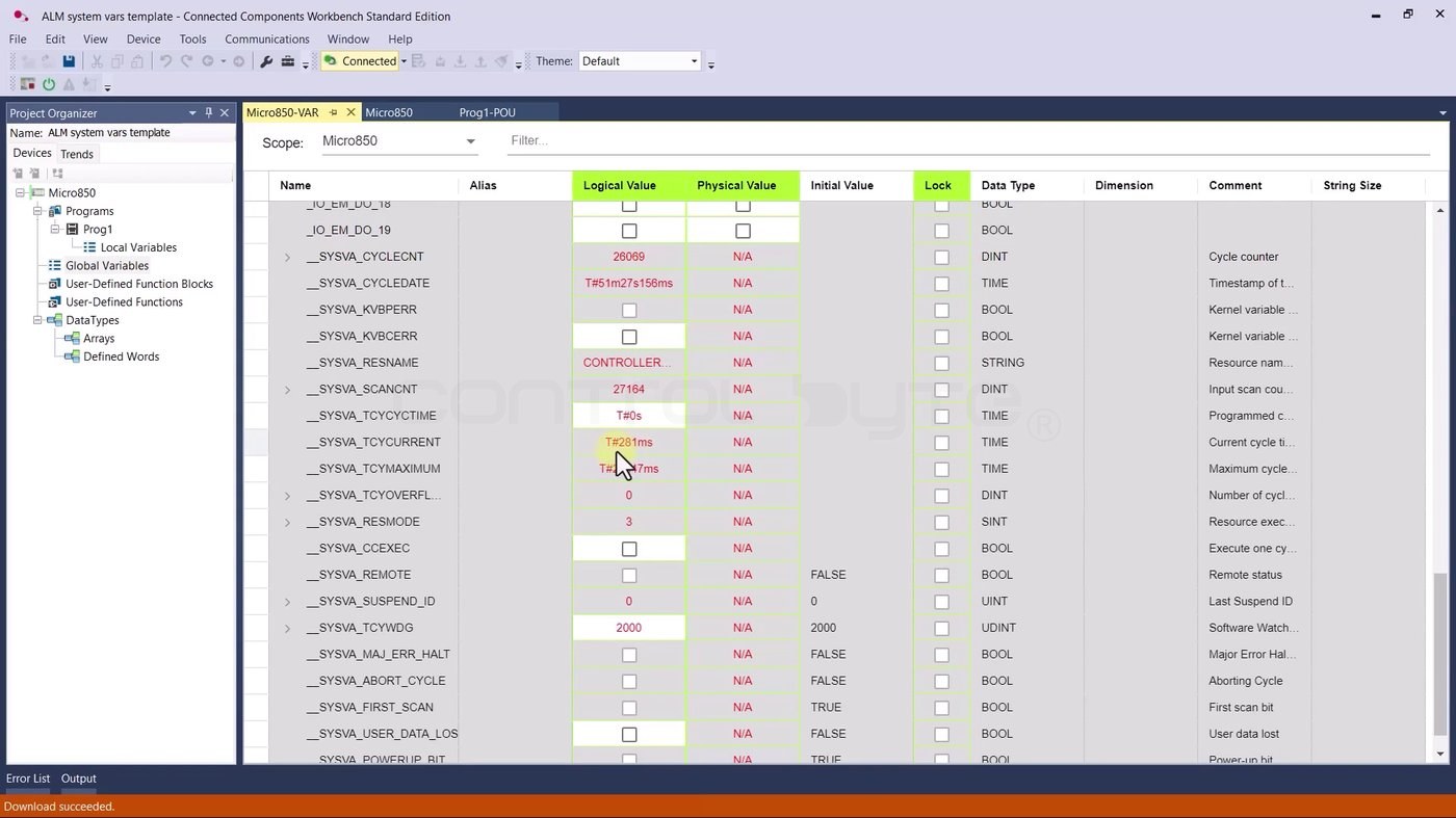
On their own these numbers may not mean much yet, but they are exactly what you reach for when a machine misbehaves or when you need to optimize a long program.
Using the First Scan bit
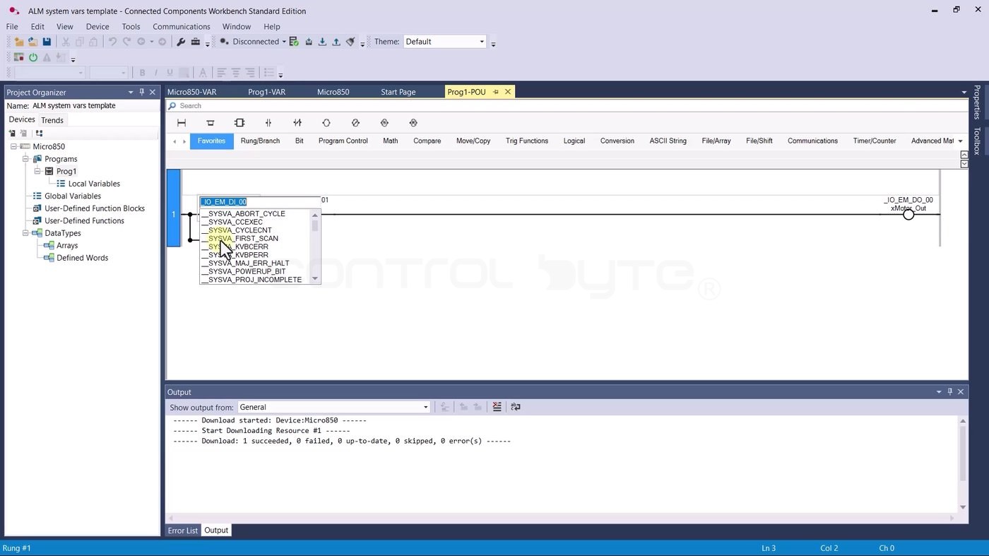
Now the interesting part. Instead of the physical start button, we want the rung to energize itself once, automatically, right after the controller starts. Go back to PROG1, disconnect from the simulator, click the first contact and pick the first scan flag from the list - __SYSVA_FIRST_SCAN.
The result: the rung starts itself
Download again to the simulator and switch to RUN. The first output turns on immediately - and there is no start button in the circuit anymore.
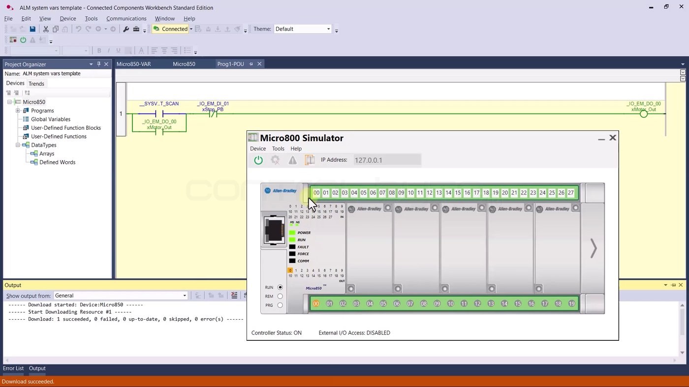
Right after entering RUN, when the controller executed its very first program scan, __SYSVA_FIRST_SCAN was set for one scan and drove the output to a TRUE state. That is precisely what a first scan bit is for: running initialization actions once, at start-up.
RUN vs PRG mode
To see the effect clearly, switch the simulator to PRG mode. PRG mode is effectively the controller-stopped state - the program does not execute, so all outputs are deactivated.
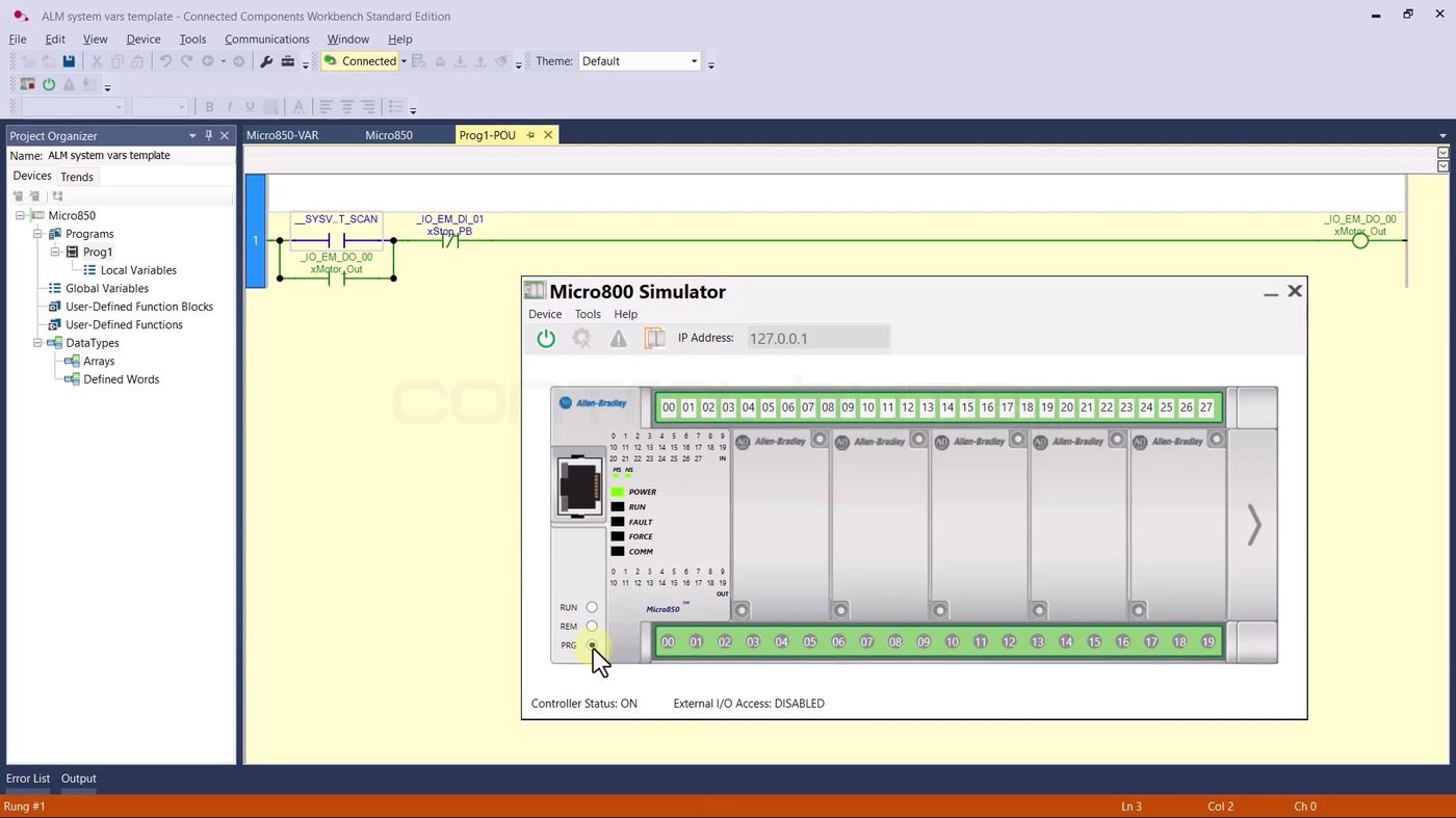
Switch back from PRG to RUN and the first scan fires again, re-triggering the initialization action. This RUN/PRG cycle is the easiest way to prove to yourself that the first scan bit really is a one-shot at start-up.
Where system variables help in practice
Once you know they exist, system variables show up everywhere in real projects:
- Initialization - use
__SYSVA_FIRST_SCANto preset setpoints, clear buffers or reset state exactly once when the controller starts. - Diagnostics and optimization - watch
__SYSVA_TCYCURRENTand__SYSVA_TCYMAXIMUMto catch a scan time that grows as your program does. - Health monitoring - a rising
__SYSVA_CYCLECNTconfirms the controller is scanning, which is handy to expose to an HMI or SCADA. - Safe failure - write
__SYSVA_ABORT_CYCLEto force a controlled fault when your logic detects a condition it must not run through.
For more ladder and Structured Text foundations on this platform, see our Allen-Bradley Micro800 PLC programming for beginners guide.
Frequently asked questions (FAQ)
What is the first scan bit in a PLC?
It is a system flag that is TRUE for exactly one program scan right after the controller enters RUN. In Connected Components Workbench it is __SYSVA_FIRST_SCAN. You use it to run one-time initialization actions at start-up.
How do I read the PLC cycle time in CCW?
Read the __SYSVA_TCYCURRENT system variable for the current scan time and __SYSVA_TCYMAXIMUM for the maximum recorded scan time. Both appear in the Global Variables table and update in real time.
Do system variables need any special code?
No. They are exposed as ordinary global tags. You read or write them directly in ladder or Structured Text, just like any other variable.
How do I force a controller fault from the program?
Write TRUE to __SYSVA_ABORT_CYCLE. The controller aborts the cycle and goes into fault - useful as a safe stop when your logic detects an unrecoverable exception.
Summary
System variables turn the controller's internal state into tags you can use directly: the first scan pulse for initialization, scan-time variables for diagnostics and optimization, and fault flags for safe failure. The First Scan exercise above is small, but the pattern - run something once at start-up - is one you will reuse in almost every serious program. If you want to learn PLC programming step by step and apply it to real projects, check out our Allen-Bradley Micro800 PLC programming course.

Author