A variable name has exactly one job: let anyone move from the program to the cabinet and back without asking a single question.
Picture it. The motor will not start. You open the program and read the coil: xContactor_Cmd_K1. You go to the schematic, page 10, and find -K1. You measure the voltage across terminals A1 and A2. Three steps, no guesswork.
Call that same variable Motor or Out1 and the path breaks at step two. This article lays out the naming convention we use on our Micro850 training station with a PowerFlex 525 drive, and the reasoning behind each part of it. It applies to Connected Components Workbench, but the thinking transfers to any platform.

The anatomy of a name
Every name has four parts, always in the same order:
x   Contactor   _   Cmd   _   K1
│       │           │         │
│       │           │         └── tag from the schematic
│       │           └──────────── signal role
│       └──────────────────────── object
└──────────────────────────────── data type
Read it from the right: on the schematic it is K1, this is a command, it drives a contactor, and it is a BOOL.
Part 1: the type prefix
One lowercase letter, so you never have to open the variable table to check what you are holding.
| Prefix | Data type | Example |
|---|---|---|
x | BOOL | xPushButton_Start_S1 |
i | INT | iPotentiometer_Value_R1 |
ui | UINT | uiPotentiometer_Setpoint_R1 |
di | DINT | diCounter_Parts_Total |
udi | UDINT | udiTotal_Cycles |
r | REAL | rMotor_Speed_Actual |
w | WORD | wStatus_VFD_T10 |
s | STRING | sRecipe_Name_Active |
t | TIME | tDelay_Start_Ramp |
Only x may go into a contact or a coil. Every other prefix is a warning that you are looking at a value, not a bit.
Part 2: the object
What the thing physically is, not what it does: PushButton, Selector, EStop, LimitSwitch, Contactor, Motor, MotorProtection, VFD, Potentiometer, SafetyRelay, Lamp.
Part 3: the signal role
What this particular signal carries. Four roles come back constantly:
| Role | Meaning | Direction |
|---|---|---|
Cmd | a command from the controller, what we want | output |
State | an internal state held by the program | memory |
OK | confirmation that a condition is met | input |
Ready | the device is able to run | input |
Part 4: the tag from the schematic
The last part is exactly the marker used on the drawing, without the hyphen: S1, K1, Q1, T10, R1.
The hyphen on the schematic (-S1) follows IEC 81346 and marks a product, that is a physical item. We drop it in the variable name only because Connected Components Workbench does not accept a hyphen in an identifier.
The device letter itself is not a free choice - IEC 81346-2 fixes it:
| Letter | Class | Example on our station |
|---|---|---|
| A | assembly, module | -A1 Micro850 controller |
| F | protection | -F1, -F2, -F10 |
| G | power supply | -GB1 |
| K | relay, contactor | -K0, -K1, -K2, -K3 |
| M | motor | -M1, -M2, -M3 |
| Q | power circuit switching | -Q1 motor protection switch |
| R | resistance | -R1 10 kOhm potentiometer |
| S | control device | -S1 to -S7 |
| T | converter | -T10 PowerFlex 525 drive |
| X | terminal, connector | -X1, -X4, -X5 |
Capitals and underscores
These two questions come up more than any other.
Capital letters
- the type prefix stays lowercase:
x,i,ui,di,udi,r,w,s,t - every other part opens with a capital
- inside one part the words run together, each with a capital:
PushButton,MotorProtection,RunFwdCmd - never ALL CAPS, never all lowercase
Underscores
- one underscore between parts, never inside a part
xPushButton_Start_S1has three parts: object, role, tagxPush_Button_Start_S1is wrong, it splits the object in twoxpushbuttonstartS1is wrong, there are no parts at all
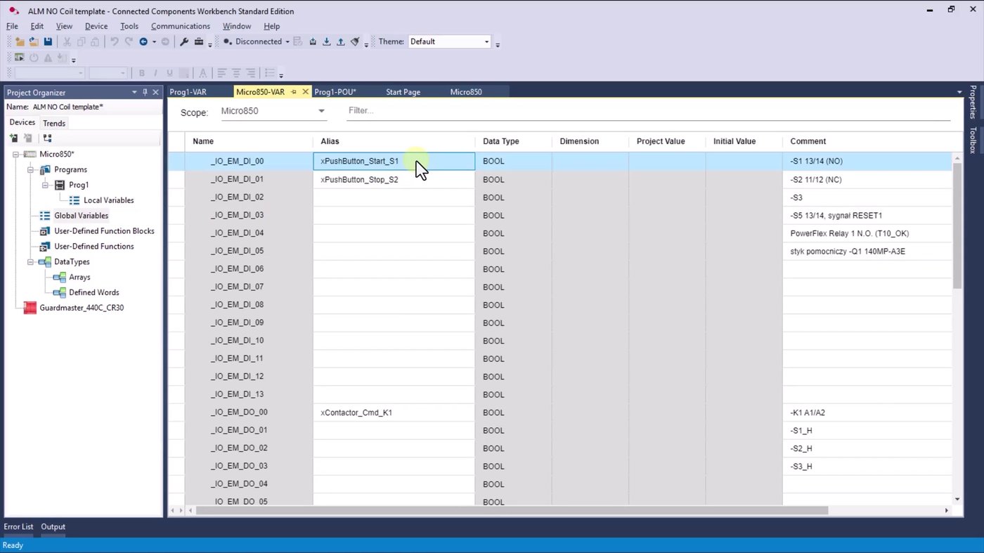
One exception: _IO_EM_DI_00 is Rockwell's own system name, with a leading underscore and all capitals. CCW does not let you change it, and there is no reason to - your own name goes in the Alias column next to it.
Terminal numbers already tell you the contact type
The comment on a variable reads -S1 13/14 (NO). That numbering follows EN 50005 and IEC 60947-5-1, and it is two digits:
- first digit - the number of the contact block inside the device
- second digit - the function: 1 and 2 form a break contact (NC), 3 and 4 form a make contact (NO)
| Terminals | Type | Typical devices |
|---|---|---|
| 13/14 | NO | start button, reset button, auxiliary contact |
| 11/12 | NC | stop button, e-stop, safety limit switches |
| 21/22 | NC | e-stop, second channel |
So the terminals alone are enough. The (NO) or (NC) note in the comment is a courtesy, not the source of truth.
The convention applied: a worked I/O map
This is what it looks like on a real station.
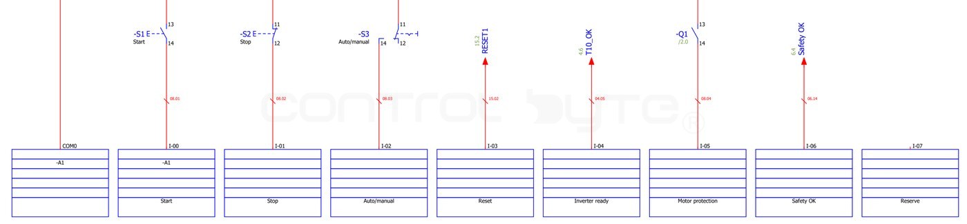
Digital inputs
| Channel | Description | Device | Contact | Variable |
|---|---|---|---|---|
| I-00 | Start | -S1 | 13/14 NO | xPushButton_Start_S1 |
| I-01 | Stop | -S2 | 11/12 NC | xPushButton_Stop_S2 |
| I-02 | Auto / manual | -S3 | 11/12, 14 | xSelector_AutoManual_S3 |
| I-03 | Reset | -S5 | 13/14 NO | xPushButton_Reset_S5 |
| I-04 | Drive ready | -T10 | - | xVFD_Ready_T10 |
| I-05 | Motor protection | -Q1 | 13/14 NO | xMotorProtection_OK_Q1 |
| I-06 | Safety OK | -CR30 | - | xSafety_OK_CR30 |
Digital outputs
| Channel | Description | Device | Variable |
|---|---|---|---|
| O-00 | Motor start | -K1 A1/A2 | xContactor_Cmd_K1 |
| O-01 | Start button LED | -S1_H | xPushButtonLamp_Start_S1 |
| O-04 | Drive stop | -T10 | xVFD_StopCmd_T10 |
| O-05 | Drive run forward | -T10 | xVFD_RunFwdCmd_T10 |
| O-06 | Drive run reverse | -T10 | xVFD_RunRevCmd_T10 |

Analog
| Channel | Description | Device | Variable |
|---|---|---|---|
_IO_P1_AI_00 | Potentiometer 0-10 V | -R1 | uiPotentiometer_Setpoint_R1 |
_IO_P2_AO_00 | Drive speed reference 0-10 V | -T10 | uiVFD_SpeedRef_T10 |
Analog channels are UINT in CCW, not BOOL. That is exactly why the prefix is ui and never x.
Safety devices are not in the variable table
On this station the e-stop -S4 and the safety limit switches -S6 and -S7 do not reach the Micro850 at all. They are wired into a configurable safety relay, and the controller receives a single combined Safety OK signal on I-06.
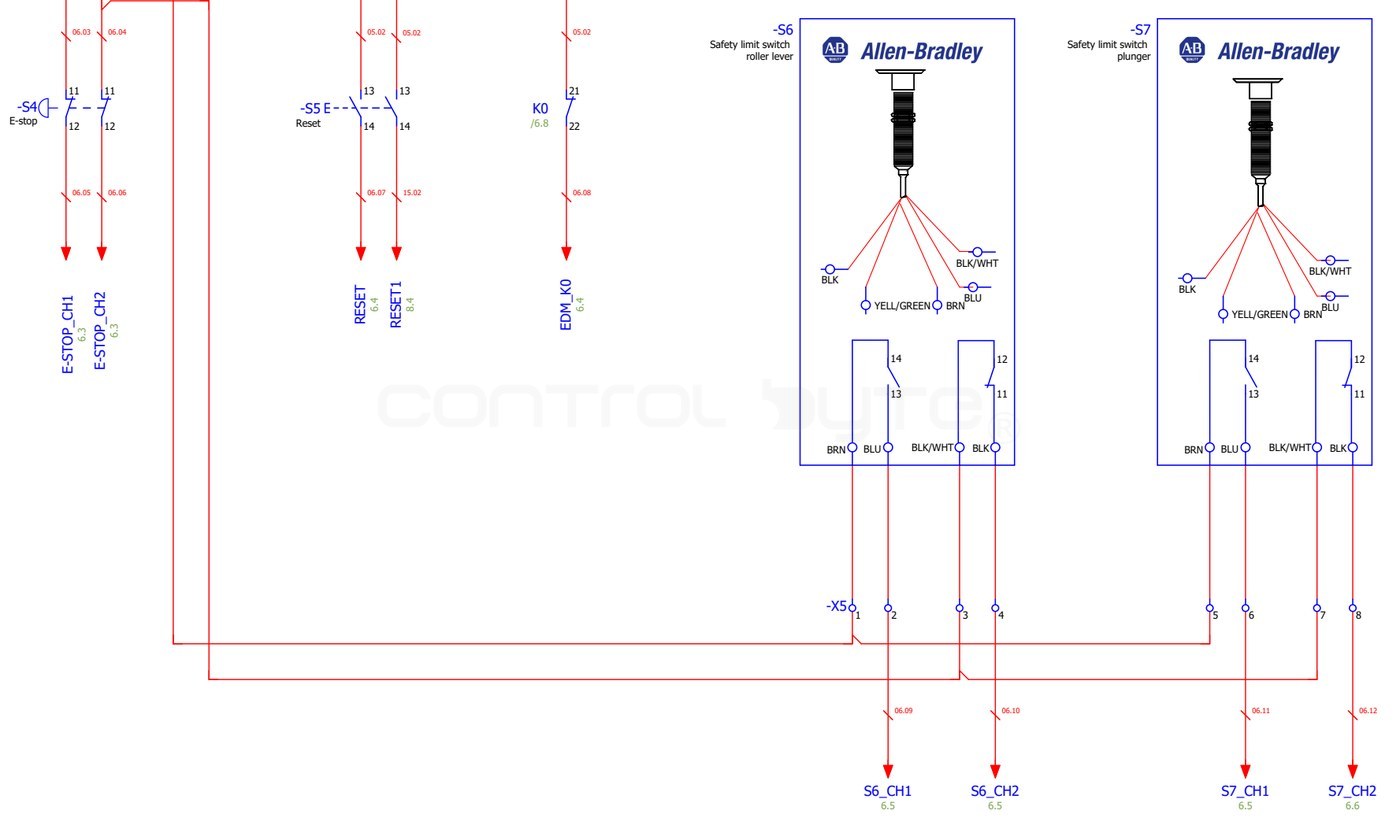
Worth saying out loud when you teach this. A student looks for the e-stop in the variable table, does not find it, and assumes something is missing. Nothing is missing - the safety function lives outside the program logic on purpose.
Command, confirmation, state
Three different things that beginners collapse into one:
| Variable | What it actually says |
|---|---|
xContactor_Cmd_K1 | the controller asks for the contactor to pull in |
xMotorProtection_OK_Q1 | the protection confirms it is healthy |
xMotor_1_AlarmState | the program remembers that an alarm occurred |
A command is not proof of execution. The coil xContactor_Cmd_K1 can be TRUE while the motor stands still: a burnt contactor coil, welded contacts, a broken wire. That is why on real machines the auxiliary contact is read back and compared against the command, and a mismatch is raised as an alarm. Wire K1 back to a spare input and that variable would be called xContactor_Fb_K1, from feedback.
Six rules
1. Never encode NO or NC in the name. Wrong: xPushButton_Stop_NC_S2. Rewire the button to a different contact block and the name starts lying.
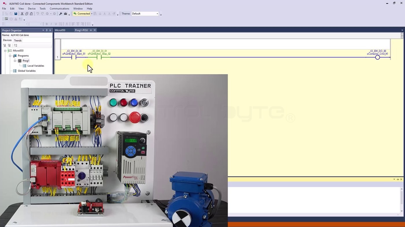
The screenshot above is the reason. xPushButton_Stop_S2 comes from an NC contact in the panel, yet in the rung it sits as a normally open contact - which is why it shows green while nobody is pressing it. Two different facts, neither of which belongs in the name. The contact type goes in the comment and on the schematic.
2. Never put the address in the name. xStart_DI00 looks helpful until someone moves the button to another channel. Then the name lies. The address lives in the Name column, and only there.
3. Leave reserves empty. Unused channels get an alias the day something is wired to them, not before.
4. One device, one tag. If the drawing says -S1, the program says _S1. No _S01, no _PB1, no variants.
5. Always name in English. English is the common language of automation - documentation, forums and support all run on it. Use English unless the customer's own standard says otherwise.
6. The underscore separates parts, not words. xPushButton_Start_S1, not xPush_Button_Start_S1.
Checklist before you start programming
- every channel in use has an alias
- every alias ends with the schematic tag
- every comment reads
-Xn terminals (type) - reserve channels are still empty
- no alias contains an address
- no alias contains NO or NC
- the prefix matches the data type
Frequently asked questions (FAQ)
Why put the data type in the variable name at all?
Because it tells you instantly whether a variable may go into a contact or a coil. Only a BOOL (x) may. Seeing uiVFD_SpeedRef_T10 in a rung is an immediate signal that something is wrong.
Why not write NO or NC in the name?
Because the contact type is a property of the wiring, not of the signal. Move the wire to another contact block and the name becomes false. The comment and the schematic carry that information.
Should variable names be in English even on a local project?
Yes, unless the customer has their own standard. Documentation, support and forums all run in English, and mixed-language tables are painful to maintain.
What if the schematic has no tag for a device?
Then the schematic needs fixing first. The whole convention rests on one tag pointing at exactly one device - if a tag is duplicated or missing, settle it on the drawing before you name anything in the program.
Summary
A good variable name is not decoration, it is a link between the program and the cabinet. Four parts - type, object, role, schematic tag - are enough to make that link hold: xContactor_Cmd_K1 tells you what it is, what it does and where to find it with a multimeter.
To see this convention in action on a real rung, read our walkthrough of normally open contacts and coils in ladder logic, and take a look at the ControlByte PLC Trainer that all these examples come from. If you want a structured path through PLC programming, see our Allen-Bradley Micro800 PLC programming course.

Author