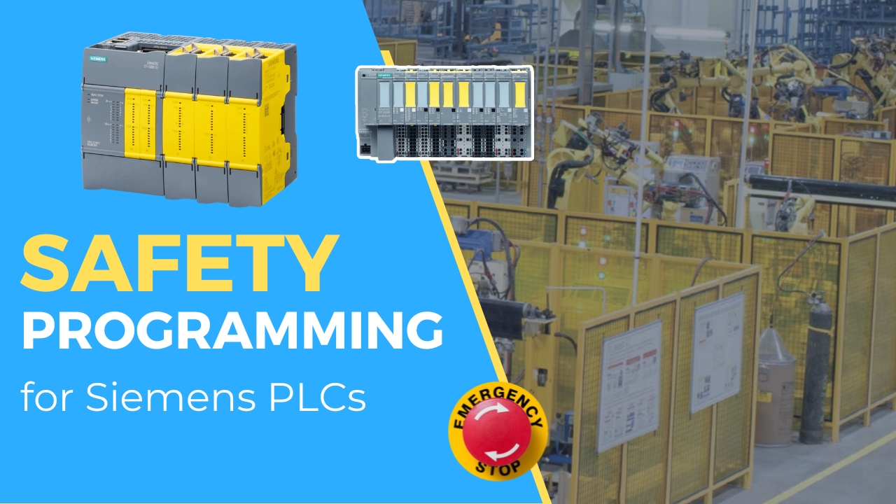
The emergency stop button, commonly known as E-Stop or simply the "mushroom button," is one of the key safety elements in machines and production lines. Its role is simple: immediately stop the technological process in a situation threatening operator health or machine damage.
In this article, we will look at the basic requirements and categories of emergency stop, E-Stop wiring methods, differences between stop categories 0 and 1, and implementation examples in safety systems.
Theory and Normative Requirements
The emergency stop function is defined in ISO 13850, the electrical side (colors, stop categories, circuits) in IEC 60204-1, and the required safety level of the control system is evaluated according to ISO 13849-1. Together they say that every E-Stop must meet several basic conditions:
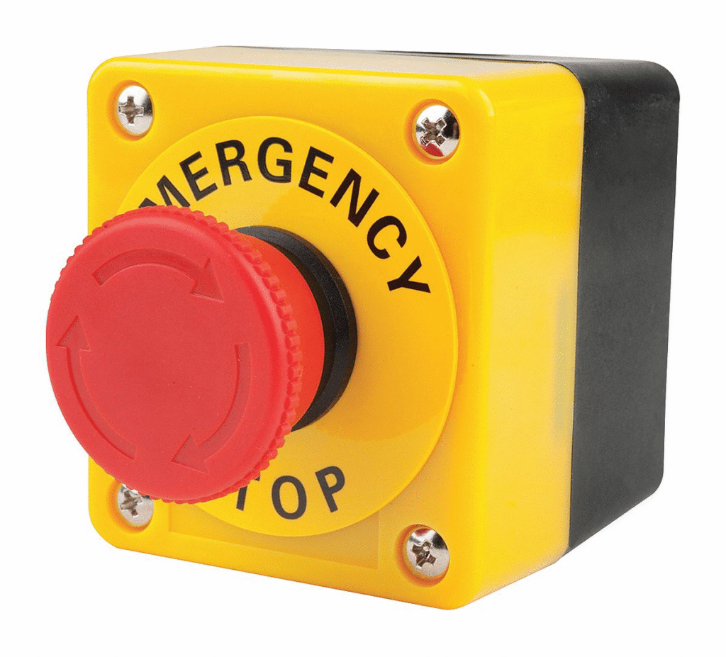
- Red mushroom-head button on a yellow background
- Easily accessible to the operator
- Latching action - after pressing, the button must remain in the emergency position until manually released
- Immediate process stop in category 0 or 1
- Reset possible only under safe conditions (additional reset button in case of multiple E-Stops)
Emergency Stop Categories
Category 0 - Immediate power disconnection. Example: after pressing E-Stop, the contactors disconnect the power circuit, and the motor stops by coasting.
Category 1 - Controlled stop with ramp. Example: after pressing E-Stop, the drive receives a Quick Stop signal (e.g., SS1 in a frequency inverter/servo amplifier), and only after a set time is the power cut by contactors or the STO (Safe Torque Off) function.
E-Stop Wiring Diagram
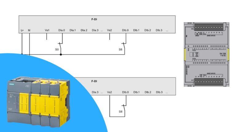
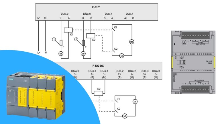
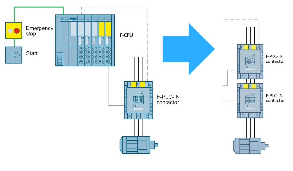
A typical E-Stop circuit consists of:
- A button/pull cord with 1 or 2 normally closed contacts with direct opening action
- One or two contactors in the power circuit
- An optional reset button
- A safety relay or safety controller
Source: www.siemens.com
Two contacts and two contactors with monitored feedback contacts form a two-channel (redundant) architecture. This is the basis for the high safety levels such as PL d/PL e or SIL 3, but the final level always has to be verified with ISO 13849-1 calculations (component reliability, diagnostic coverage and common cause failures), not only by counting channels.
Implementation in the Safety PLC
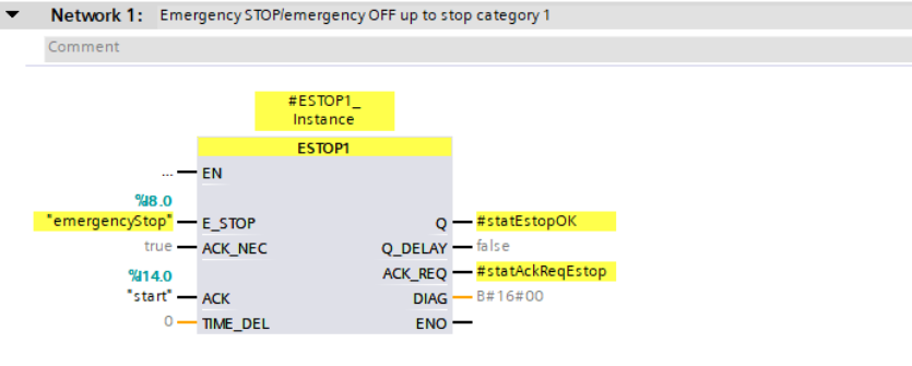
In TIA Portal, STEP 7 Safety provides ready-made safety instructions, such as ESTOP1, which enable implementing the emergency stop function in categories 0 and 1. This block allows for:
- Handling single or multiple E-Stop buttons
- AND logic implementation
- Delayed shutdown function (for category 1)
- Reset and ACK signal handling
How Does an Emergency Stop Button Work?
An emergency stop button is a push button with normally closed (NC) contacts and a latching mechanism. In normal operation the contacts are closed and the safety relay or safety PLC sees a high signal. When the button is pressed, the contacts open and the safety circuit removes power from the hazardous motion of the machinery. Using NC contacts is a fail-safe principle: a broken wire, a loose terminal or a missing 24 V power supply looks exactly like a pressed button, so the fault stops the machine instead of hiding it.
IEC 60947-5-5 describes the device itself. The most important features are:
- Direct opening action - the contacts are forced apart mechanically by the actuator, so even a welded contact is pulled open when the button is pressed.
- Mechanical latching - once the button is activated, it stays in the pressed position. It can only be released by a deliberate human action, for example by twisting or pulling the mushroom head (or with a key on some versions).
- Big red, easy to hit actuator - a mushroom or palm type head that can be operated with the palm of the hand, on a yellow background color so it is eye-catching on the control panel.
Inside the button a spring-loaded mechanism opens the contacts, and many devices have an additional self-monitoring contact that detects when a contact block falls off the actuator.
Where to Install Emergency Stop Switches
The location of each emergency stop device comes from the risk assessment. In practice:
- at every operator station and control panel, and next to every place where an operator can reach a hazard,
- readily accessible and operable without reaching over moving parts or opening an enclosure,
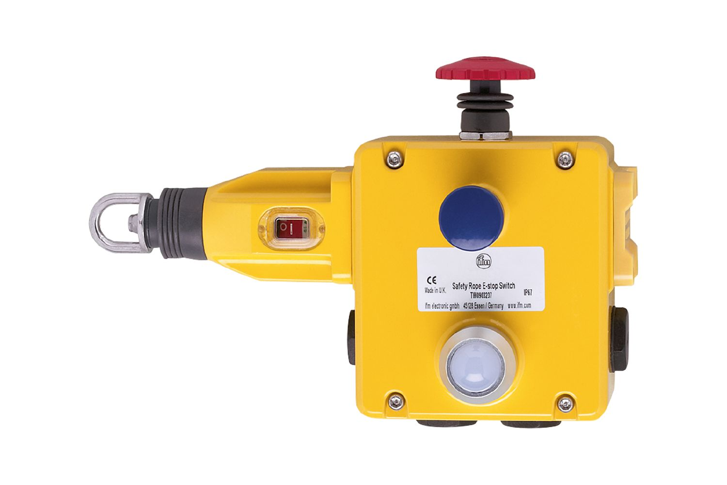
- along long conveyors as a pull-wire (rope) switch, so the line can be stopped from any point,
- on portable operator panels and teach pendants, together with an enabling switch.
The emergency stop is a complementary protective measure. It does not replace guards, interlocked doors or light curtains, which must prevent access to the hazard in the first place - the E-Stop is the last resort for a single human action in the event of an emergency.
Reset and Restart After an Emergency Stop
Releasing a latched E-Stop must never restart the machine by itself. The correct sequence is:
- The cause of the emergency is removed and the area is checked.
- The operator releases (unlatches) the emergency stop switch.
- The operator presses a separate reset button. The safety relay or safety PLC checks that both channels are closed and the contactor feedback is correct, and only then enables the outputs.
- The machine is started with a normal start command.
This protects people from a machine that starts unexpectedly. In the safety program, the reset is usually done on a falling edge of the reset signal, so a reset button stuck in the pressed position cannot acknowledge the safety function. More about connecting E-Stops and other safety devices to a fail-safe controller can be found in our guide to safe inputs of safety controllers.
Emergency Stop - FAQ
Are emergency stops normally open or closed?
The safety contacts of an emergency stop button are normally closed. Pressing the button opens them and interrupts the safety circuit. Some buttons also have a normally open auxiliary contact, but only as a signal for the PLC or HMI, never for the safety function.
Which stop category can an emergency stop use?
According to IEC 60204-1 and ISO 13850, the emergency stop must work as stop category 0 (power is removed immediately) or stop category 1 (controlled stop, then power is removed). Stop category 2, where power stays on the actuators, is not allowed for an emergency stop.
Can emergency stop buttons be guarded?
A shroud or collar around the button can be used to prevent accidental actuation, for example on a portable panel, but it must not make the button hard to reach or slower to activate. If the risk assessment shows that accidental activation is a real problem, the better solution is usually a different mounting position.
Should emergency stops be tested?
Yes. Every emergency stop switch should be tested regularly: press the button, check that the machine stops in the expected stop category, check that it cannot restart without a reset, and record the result. A safety PLC can also detect faults such as a short circuit between channels using test pulses.
Summary
The E-Stop button is a basic but extremely important element of safety systems. Combined with proper logic in the safety controller and appropriate selection of actuating elements (contactors, STO function in drives), it provides effective protection for operators and machines.
👉 Check out our full Safety PLC Course here
Want to master Safety PLC programming? Learn everything from safety principles to real-world configurations in our comprehensive online course.