Connecting Devices to the S7-1200 PLC Outputs
The time has come to transmit a signal from the Siemens S7-1200 PLC to actuators.
Remember, not everything can be directly connected to the controller, for example, you cannot directly connect an induction motor or solenoid valve!
Read this Siemens S7-1200 PLC tutorial to find out more about the digital outputs of this PLC. If you want the other half of the input and output story, see our article about the digital inputs of the Siemens S7-1200 PLC.
What Can You Connect to PLC Outputs?
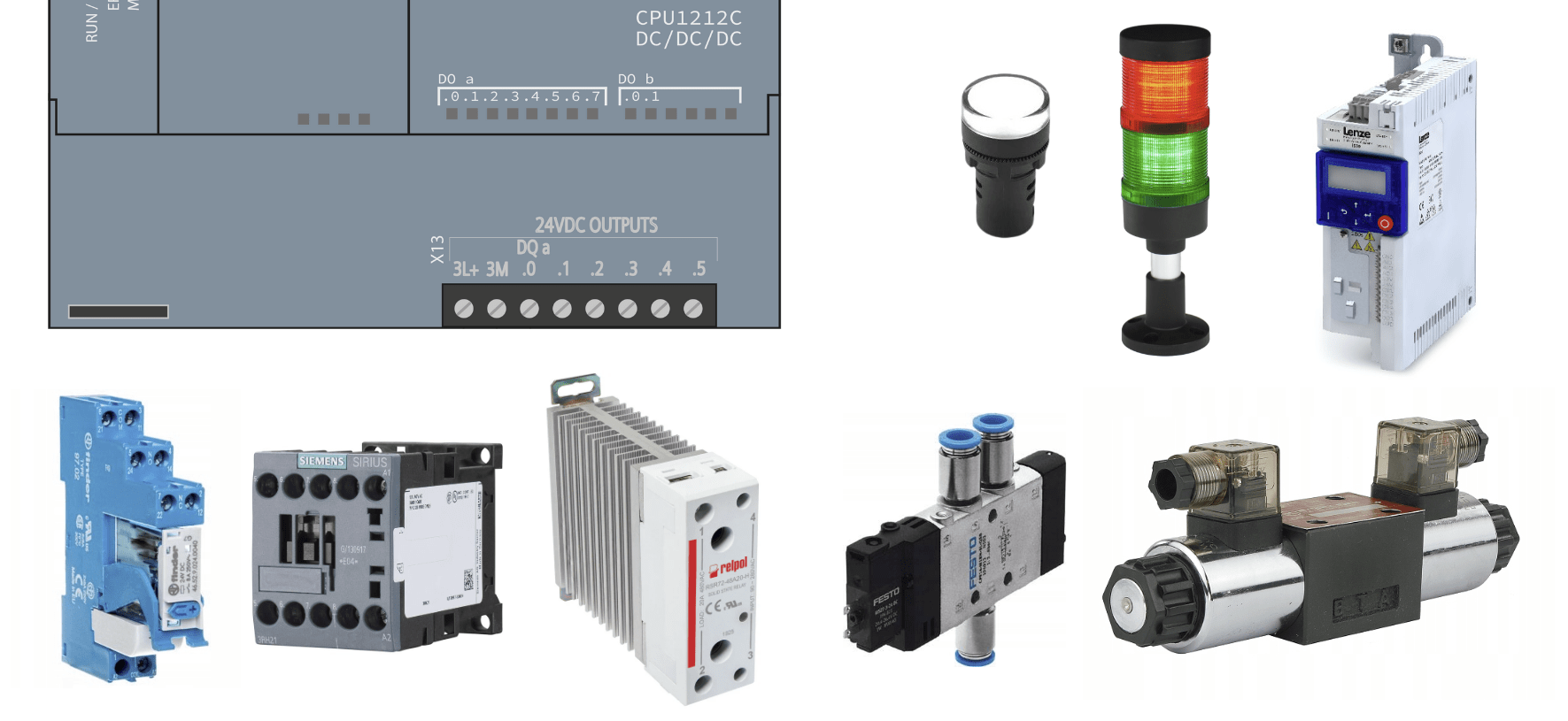
Below is a list of example devices that you can connect directly to the PLC controller.
REMEMBER! Always pay attention to the current capacity of the contacts.
| Device Type | Description | Example Product | |
|---|---|---|---|
| Signal light | Output device used to visually signal the status of a machine or process | Turck TL503AOSKQ light tower | 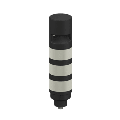 |
| Contactor | Switching device used to control electric motors and other heavy loads | Schneider Electric LC1K0901B7 9A contactor | 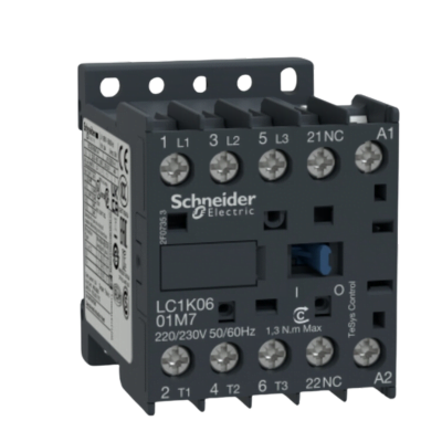 |
| Relay | Switching device used to control lower-power devices | Finder 38.51 EMR interface module | 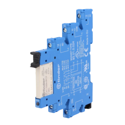 |
| Inverter | Device used to control the speed of electric motors by adjusting the supply frequency | Lenze i510 frequency inverter | 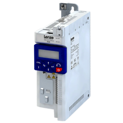 |
| Small solenoid valve | Device used to control the flow of media (often water or air) in pipelines | Festo VUVS solenoid valve | 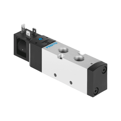 |
Transistor Outputs of the S7-1200 PLC
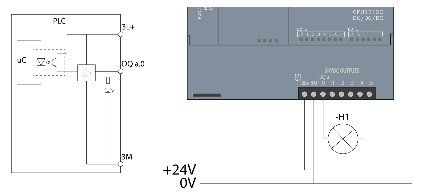
Characteristics of Transistor Outputs
- Type: Use transistors to switch loads. These can be MOSFET transistors or open-collector bipolar transistors.
- Voltage: Typically operate within a voltage range of 24V DC.
- Current: They can supply low current, usually 0.5A to 2A.
Advantages of Transistor Outputs
- Speed: Transistor outputs operate faster than relay outputs.
- Durability: They have no moving parts, resulting in longer lifespan.
Disadvantages of Transistor Outputs
- Limited current: Not designed for switching heavy loads.
- Sensitivity: They may be more susceptible to damage from voltage spikes than relay outputs.
Relay Outputs of the S7-1200 PLC
Characteristics of Relay Outputs
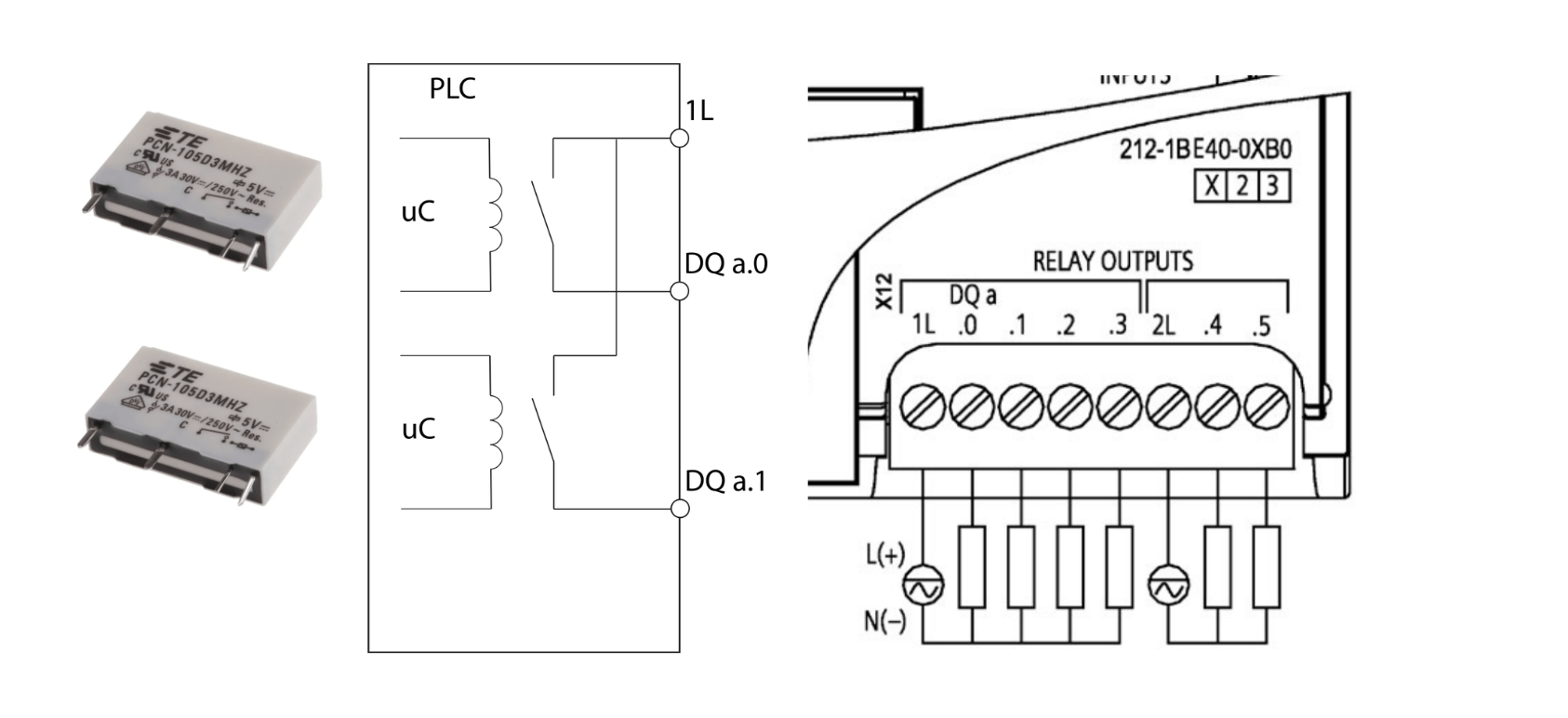
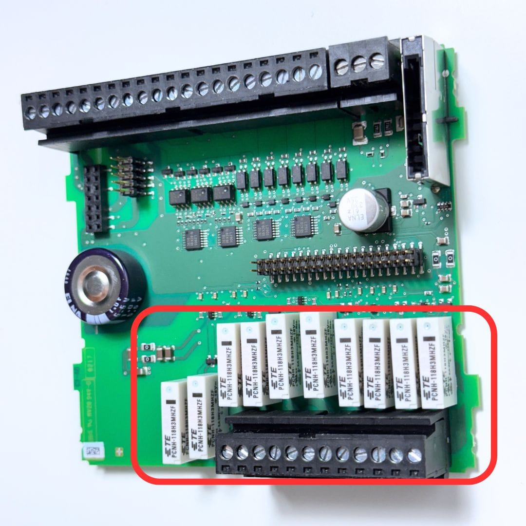
- Type: Use electromagnetic relays to switch loads.
- Voltage: Can operate with various voltages, both AC and DC.
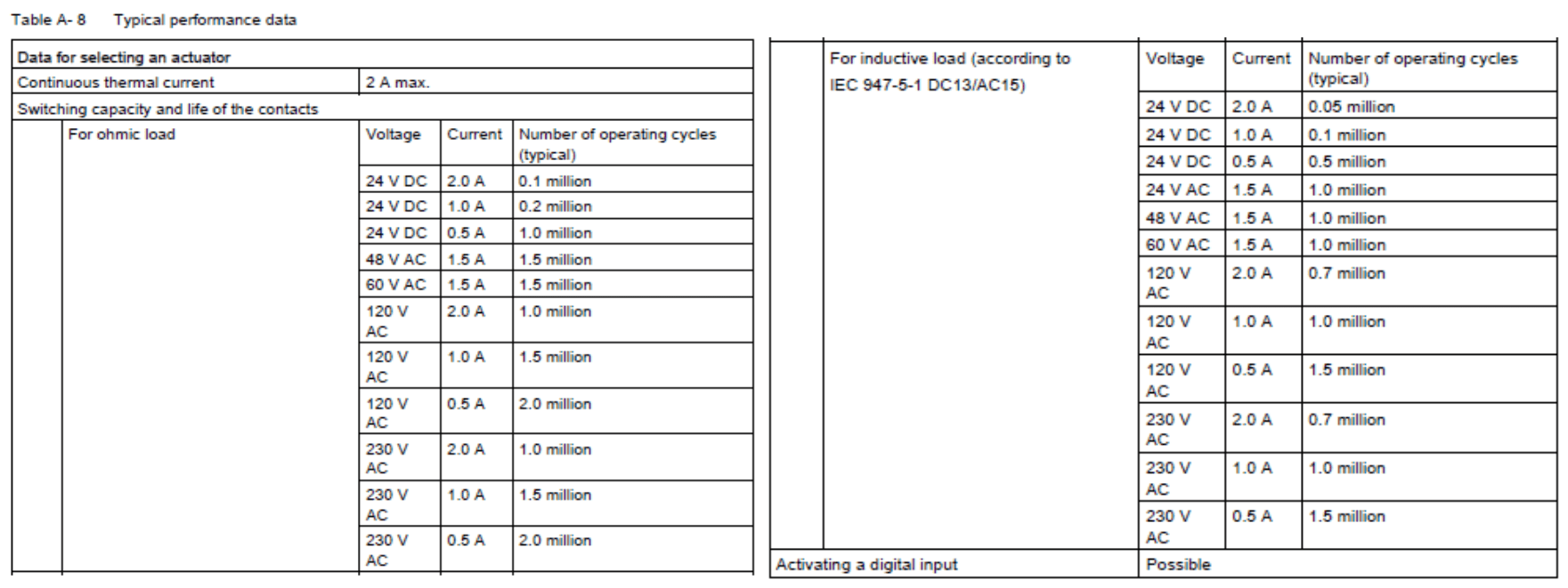
- Current: Depending on the relay type, they can switch significant loads, often up to several amps.
Advantages of Relay Outputs
- Flexibility: They can switch various voltages and types of loads.
- Isolation: Provide good isolation between the PLC and the load.
Disadvantages of Relay Outputs
- Speed: Operate slower than transistor outputs.
- Lifespan: Have moving parts, which may lead to a shorter lifespan compared to transistor outputs, especially in applications with frequent switching.
Choosing the Right Type of Outputs in the PLC
The choice between transistor and relay outputs depends on the specific application:
- If you need to switch quickly and frequently, transistor outputs may be a better choice.
- If you need to switch different voltages, especially AC, or heavy loads, relay outputs may be more appropriate.
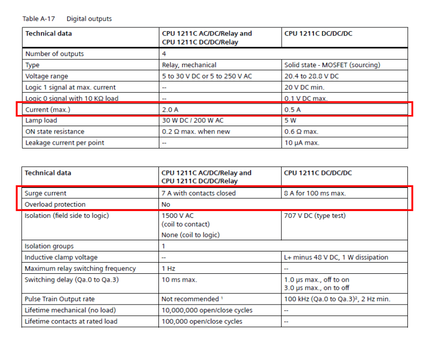
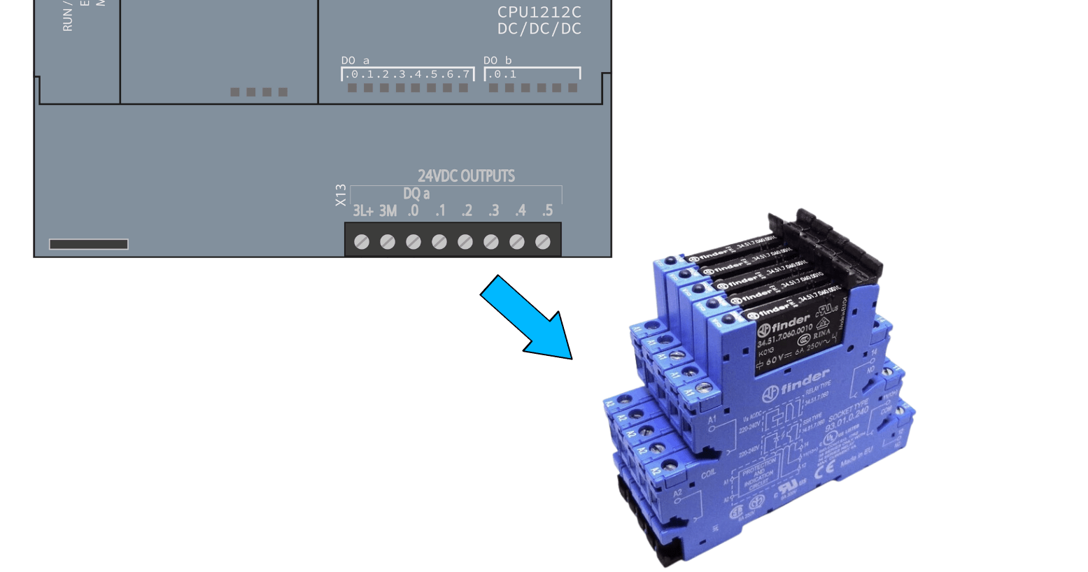
It is therefore recommended to use controllers with transistor outputs and intermediate power supply to actuators that draw more current, e.g., via interface relays or contactors.
High-Speed Outputs (PTO) of the S7-1200 PLC
Like high-speed inputs, high-speed outputs are designed to generate high-frequency signals.
Applications of High-Speed Outputs
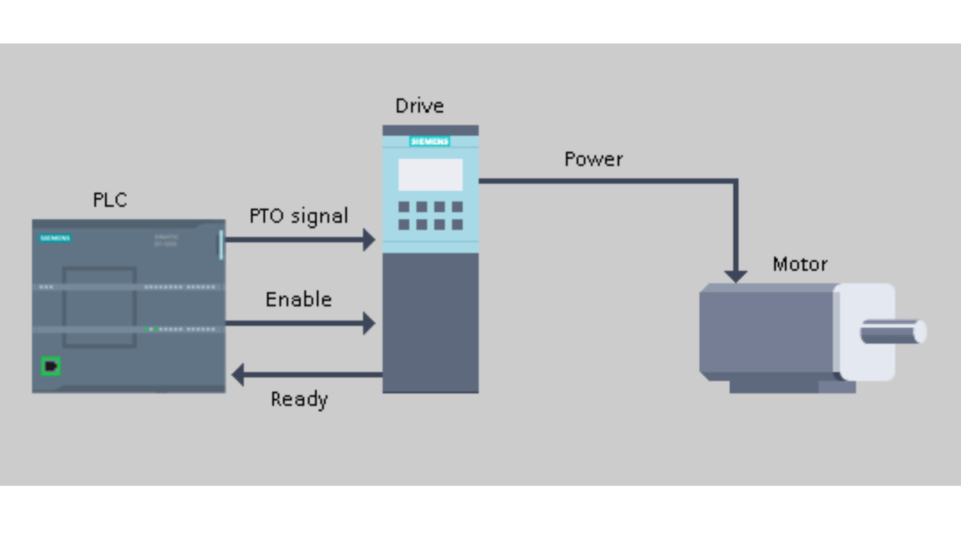
- Drive Control: Generating PTO pulses to control stepper motor and servo motor amplifiers
- Generating PWM Signals (Pulse Width Modulation): To control motor speed, light brightness, etc.
Characteristics of High-Speed Outputs
- High Frequency: Can generate signals at frequencies of tens of kHz.
- Precise Timing: Allow for accurate control of signal duration and frequency.
How PLC Digital Outputs Work
A PLC digital output (also called a discrete output) has only two states: ON and OFF. During each scan the CPU executes the program, writes the result to the process image of outputs (the Q area, for example %Q0.0) and then copies this image to the physical output terminals. The output itself is a semiconductor switch or an electromechanical relay contact that connects the field device to its power supply. That is the main difference to an analog output, which produces a variable signal such as 0-10 V or 4-20 mA to set a valve position or a drive speed reference. On the S7-1200, analog outputs come from signal modules (SM 1232) or signal boards, while digital outputs are built into every CPU.
Digital vs. Analog Inputs and Outputs in a PLC System
Every PLC system works with four basic signal types: digital inputs, digital outputs, analog inputs and analog outputs. Digital input modules read two-state signals from buttons, limit switches and sensors, analog input modules measure values such as temperature, pressure or level, and output modules send commands back to the process. In programmable logic controllers from all vendors, from the Siemens S7-1200 to Allen-Bradley CompactLogix, the same rule applies: use a digital output when the field device only needs ON/OFF control, and an analog output module when it needs a variable setpoint.
Solid-state outputs: transistor and triac
Transistor outputs are solid-state outputs for 24VDC loads (DC-only). Many PLCs also offer triac outputs, which are solid-state outputs for AC loads. Both types have no moving parts, but they have a small leakage current in the OFF state. With very low-power loads, such as some LED indicators or electronic inputs of other devices, this leakage can be enough to keep the load glowing or seen as ON. Relay contacts have no leakage, which is one reason why a dry contact is still used to pass signals between two PLCs or to another control system.
S7-1200 Output Types at a Glance
The letters after the CPU name tell you which digital output type you get: the last part of DC/DC/DC or AC/DC/RLY describes the outputs.
| S7-1200 version | Output type | Load voltage | Current rating per point | Typical use |
|---|---|---|---|---|
| DC/DC/DC | Transistor (MOSFET), sourcing | 24 V DC | 0.5 A | Signal lamps, interposing relays, valve coils, PTO/PWM pulses |
| DC/DC/RLY | Relay (dry contact) | 5-30 V DC or 5-250 V AC | 2 A | Contactor coils, AC loads, mixed voltages |
| AC/DC/RLY | Relay (dry contact) | 5-30 V DC or 5-250 V AC | 2 A | Same as above, CPU supplied from AC mains |
Additional outputs can be added with SM 1222 digital output modules (transistor or relay versions) or SM 1223 combined input and output modules. Always check the exact data in the Siemens system manual for your module, because the total current of an output group is also limited, not only the current per point.
Wiring PLC Digital Outputs on the S7-1200
Transistor outputs (DC/DC/DC)
The transistor outputs of the S7-1200 are sourcing: the output switches +24 V DC to the load, and the other side of the load goes to 0 V (M). The output group needs its own 24 V DC supply on the L+ and M terminals - if this supply is missing, the status LED on the CPU will light up, but no voltage will appear on the terminal. A typical field device is a 24 V DC signal lamp, a small pneumatic valve coil or the coil of an interposing relay. If you are not sure about the terms sinking and sourcing, read Sinking vs Sourcing: PLC input and output sensors.
Relay outputs (RLY)
A relay output is a dry contact: the PLC only closes the contact, and you bring the voltage for the load to the common terminal of the output group. This is why one group can switch 230 V AC for contactor coils while another group switches 24 V DC. Remember that all outputs in one group share the same common, so do not mix voltages within a group.
Interposing relays and inductive loads
Use an interposing relay (a relay module or SSR between the PLC and the load) when the load current is higher than the output rating, when the load needs a different voltage, or when you want a replaceable part instead of risking damage to the CPU. Coils of contactors, valves and relays are inductive loads: when they turn off they generate a voltage spike. Use a freewheeling diode for DC coils and an RC snubber or varistor for AC coils, especially on relay outputs, to extend contact life and reduce interference.
Why Are My PLC Digital Outputs Not Working?
When a digital output does not switch the field device, check these points in order:
- CPU mode: in STOP mode the outputs go to their configured substitute state (OFF by default), so the program does not control them.
- Program logic: monitor the output in TIA Portal. If the same %Q address is written in two places in the program, the last write wins.
- Status LED vs. terminal voltage: if the LED is on but there is no voltage, check the L+/M supply of the output group (transistor) or the voltage on the common terminal (relay).
- Wiring and load: measure the output with a multimeter, check the wire to the field device and the 0 V return path.
- Overload: a short circuit or a load above the rated current can damage the output point. In that case move the signal to a spare output and add an interposing relay.
On a live machine, use a watch table or force only when it is safe, because forcing an output can start a motor or move an actuator.
PLC Digital Outputs and Inputs - FAQ
Which PLC digital outputs should I use, relay or transistor?
Choose transistor outputs for frequent switching, fast signals and pulse outputs, and use interposing relays for larger loads. Choose relay outputs when you need to switch AC voltage or different voltages directly from the PLC and the switching frequency is low.
What is the output voltage of a PLC digital output?
It depends on the output type. A transistor output delivers the voltage of its own supply, on the S7-1200 that is 24 V DC. A relay output has no voltage of its own: it switches whatever voltage you connect to its common terminal, within the current ratings of the contacts.
Can a PLC digital output drive a motor directly?
No. A PLC output can switch the coil of a contactor or send a run command to an inverter, but the motor current always flows through the contactor or the drive, never through the PLC.
Where can I learn to program S7-1200 outputs in practice?
Our Siemens TIA Portal LAD/FBD course shows how to control digital outputs step by step in ladder logic and function block diagram, from simple bit logic to timers and sequences.
Learn Siemens S7-1200 PLC programming language

Allen-Bradley hardware used in our materials (Micro800 controllers, HMI panels and accessories) is supplied by our technology partner Elmark Automatyka, an authorized Rockwell Automation distributor.