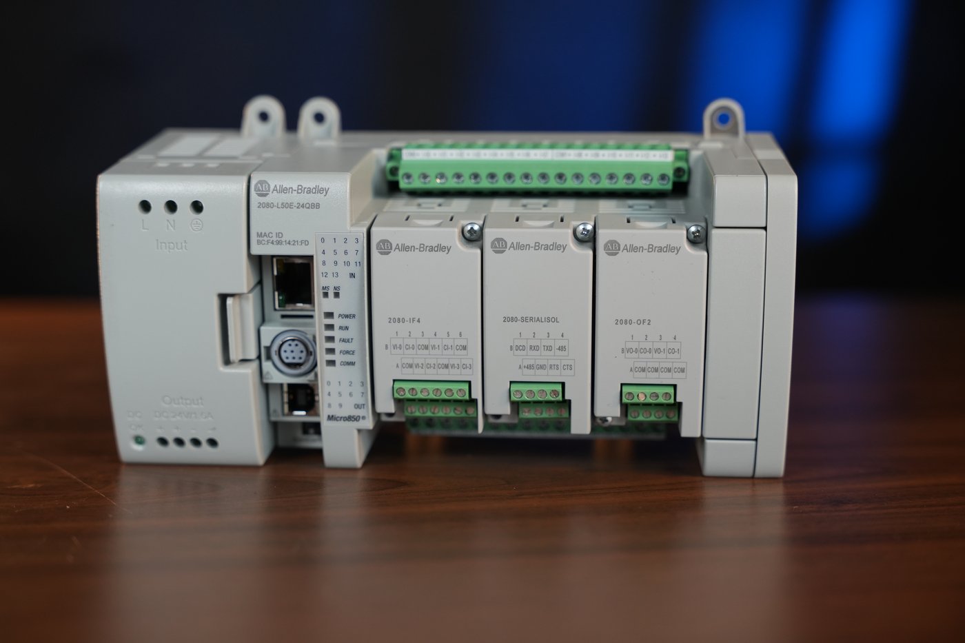
The Micro850 2080-L50E is a compact Allen-Bradley PLC that works equally well for learning automation and for real projects - in small industrial machines and simple control applications. For a practitioner, it is a controller you can deploy on the plant floor without hassle: built-in EtherNet/IP, digital inputs and outputs, and slots for analog and communication modules give you everything most small systems need. In this guide we take apart a specific set - the controller, its dedicated power supply and three plug-in modules - and show what it is made of, how to wire the power, how to address the inputs and outputs, and what this controller can really do in practice.
What the set is made of
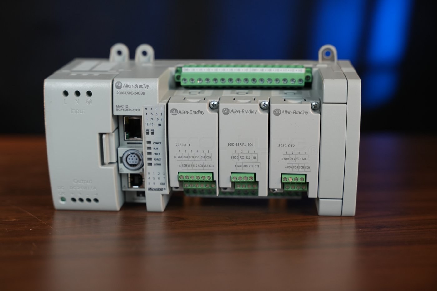
The set shown in the photos is a self-contained, fully functional control island mounted on a DIN rail. Looking from left to right, there are four functional blocks.
- 2080-PS120-240VAC power supply - converts 100-240 V AC mains into a stable 24 V DC for the controller and field circuits.
- Micro850 2080-L50E-24QBB controller - the CPU with 24 embedded I/O points, an EtherNet/IP port, a serial port and a USB programming port.
- Three plug-in modules - 2080-IF4 (analog inputs), 2080-SERIALISOL (isolated serial port) and 2080-OF2 (analog outputs), seated in the slots on the front of the controller.
- Expansion bus cap - on the right side, ready for 2085 expansion I/O modules.
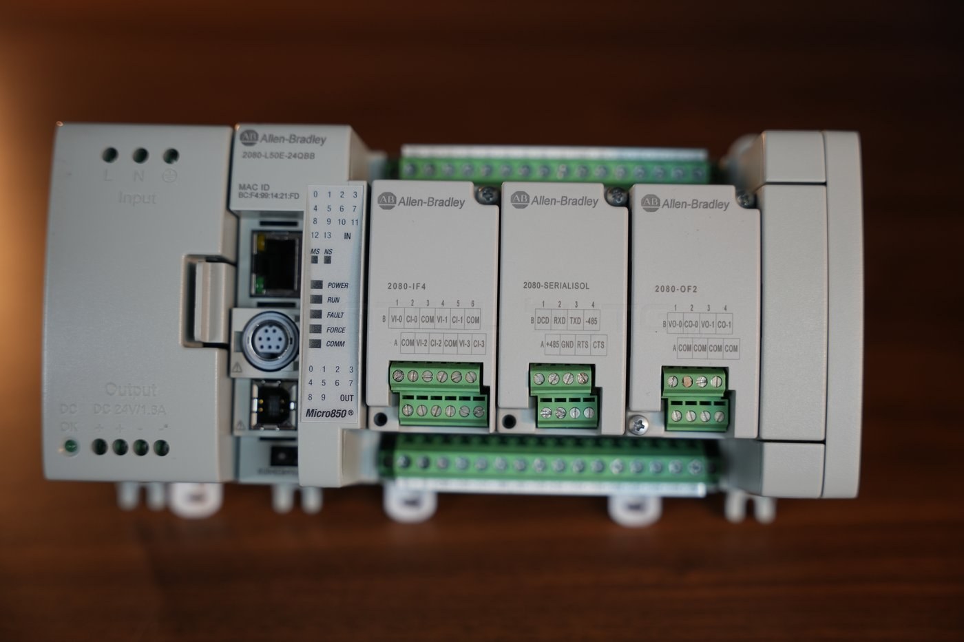
This layout is a classic example of the Micro850 architecture: a compact CPU that you extend with functions exactly where you need them - first with plug-in modules from the front, and for larger applications with expansion modules from the right side.
Micro850 2080-L50E-24QBB controller: the heart of the system
All the logic lives inside the controller. The nameplate on the back of the housing reveals the key data: catalog number 2080-L50E-24QBB, series A, firmware 22.011, EtherNet/IP support, 24 V DC / 24 V AC inputs and DC source outputs.
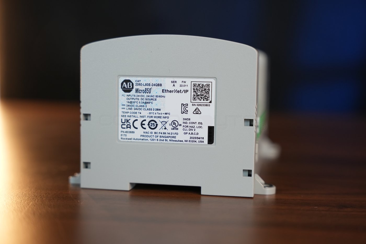
The most important features of this CPU:
| Parameter | Value |
|---|---|
| Embedded I/O points | 24 (14 digital inputs + 10 digital outputs) |
| Digital input type | 24 V AC/DC |
| Digital output type | transistor source (DC source), 1 A at 30 deg C |
| Controller power | 24 V DC (Class 2) |
| Built-in communication | EtherNet/IP, serial port, USB (programming) |
| Plug-in slots | 3 |
| Expansion modules | up to 4 (2085 series) |
| Maximum I/O | up to 132 points |
| High-speed counters (HSC) | up to 4 channels |
This controller is programmed in the free Connected Components Workbench (CCW) environment, compliant with IEC 61131-3 - Ladder Diagram (LD), Function Block Diagram (FBD) and Structured Text (ST). The built-in EtherNet/IP lets you drop it into an industrial network, expose data to an HMI panel or a higher-level controller, and the USB port is used to download the program without any extra adapters.
2080-PS120-240VAC power supply
The Micro850 runs on 24 V DC, so a typical mains installation needs a power supply. The 2080-PS120-240VAC model was designed for this family and mounts directly next to the controller.
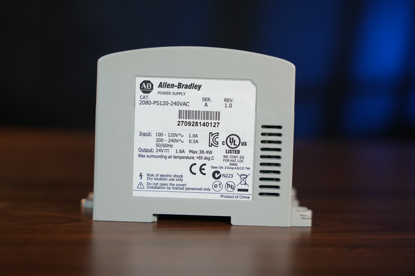
Ratings from the nameplate:
- Input: 100-120 V AC / 1.0 A or 200-240 V AC / 0.5 A, 50/60 Hz.
- Output: 24 V DC, 1.6 A, up to 38.4 W.
- Maximum surrounding air temperature: 65 deg C, dry location use only.
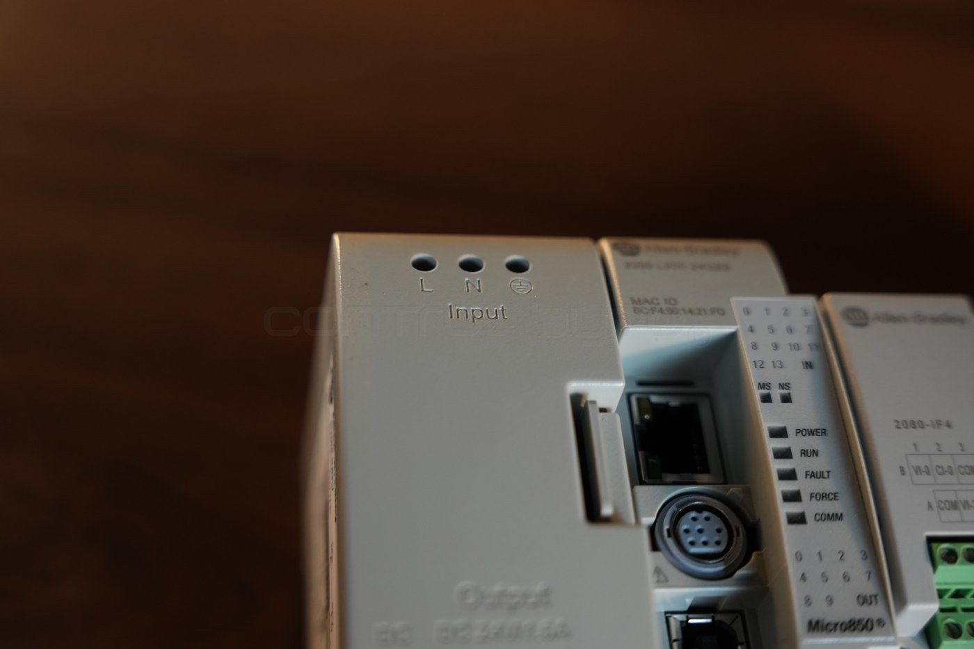
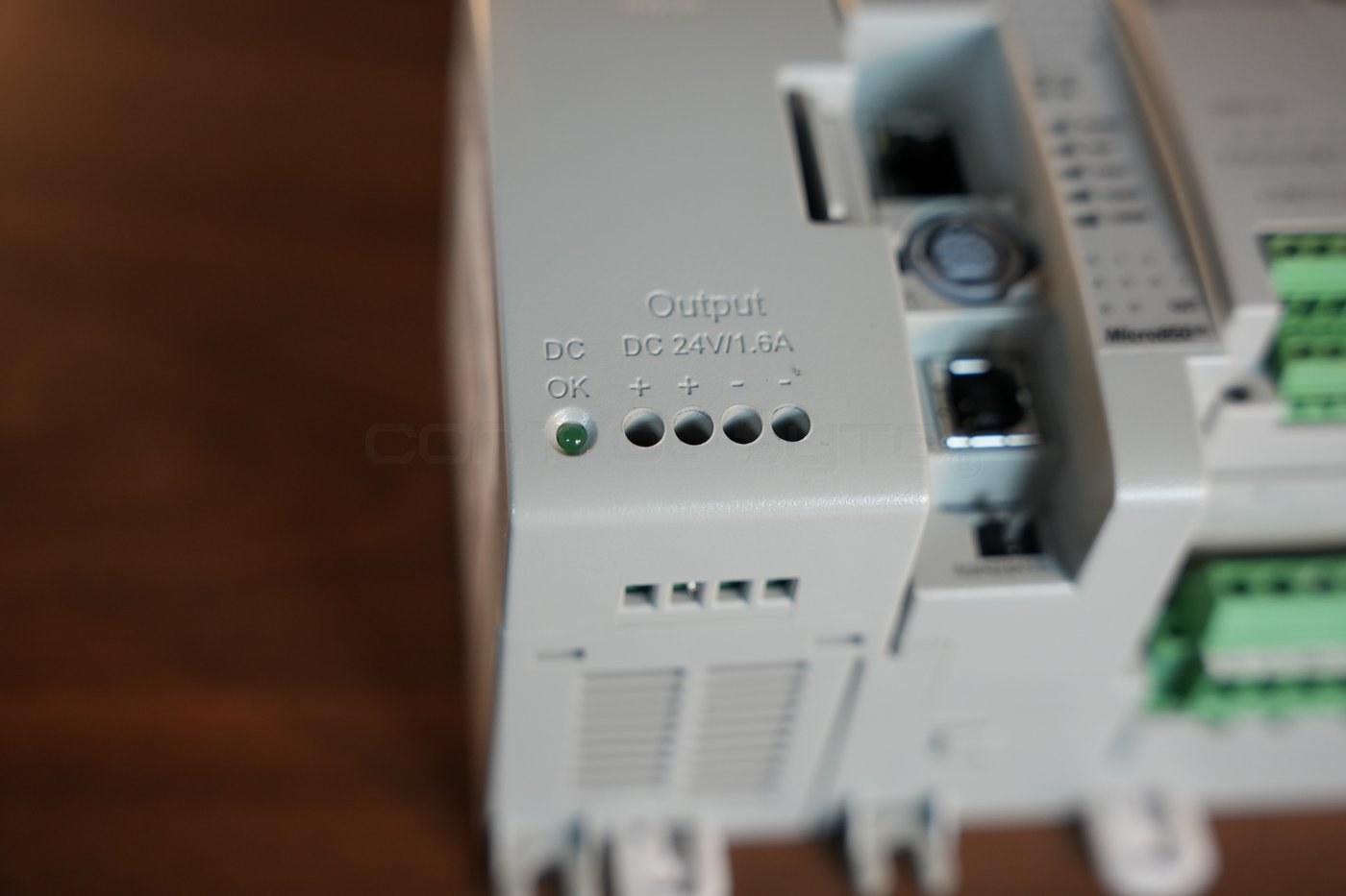
Mains voltage is connected to the terminals marked L, N and ground on the top of the power supply. This is the only place in the whole set with dangerous voltage, so the connection should be made by a trained installer.
At the bottom of the power supply are four 24 V DC output terminals (+ + - -) and a green DC OK LED that confirms the presence of the output voltage. The doubled plus and minus terminals make it easy to distribute 24 V DC to both the controller and the sensors or relays in the field.
Digital inputs and outputs of the controller
Embedded I/O is the foundation of every compact PLC. The Micro850 2080-L50E-24QBB has 14 digital inputs and 10 digital outputs, brought out to removable terminal blocks. The top block handles the inputs, the bottom one the outputs.
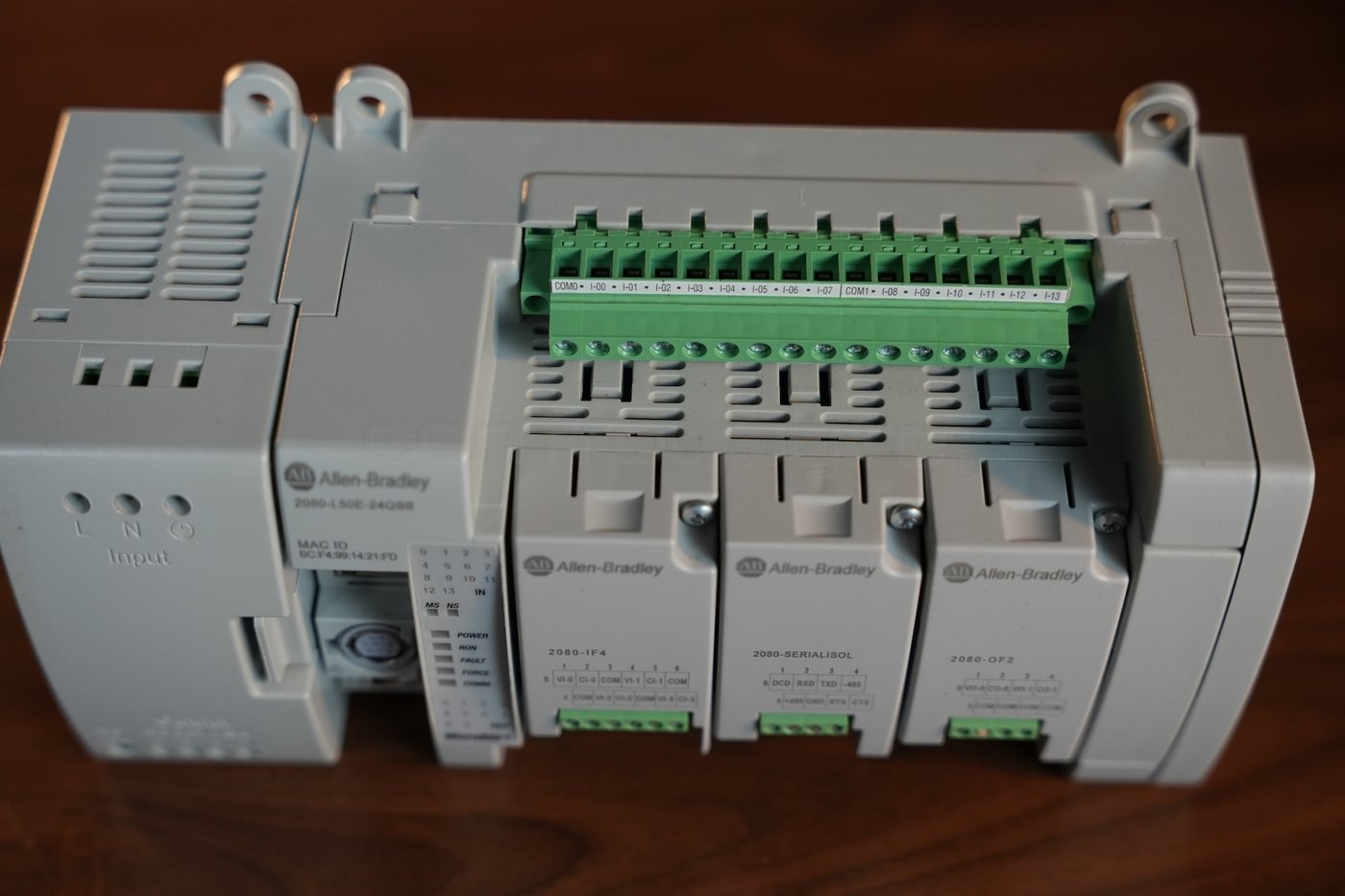
On the input block you can see the common terminals COM0 and COM1 and the channels from I-00 to I-13. Splitting them into two groups with separate common points lets you mix signal sources - for example, powering some inputs from one circuit and some from another.
In the Connected Components Workbench environment, the embedded inputs and outputs are referenced through fixed physical addresses:
_IO_EM_DI_00   // first digital input (I-00)
_IO_EM_DI_13   // last digital input (I-13)
_IO_EM_DO_00   // first digital output (O-00)
_IO_EM_DO_09   // last digital output (O-09)
The outputs are transistor source type (DC source), which means they supply plus 24 V DC to the load - ideal for driving relays, valves or the inputs of other devices. The rating is 1 A per channel at 30 deg C.
Plug-in modules: analog and communication
The three plug-in slots on the front of the controller are where the Micro850 gains functions beyond digital I/O. In our set all three slots are occupied.
2080-IF4: four analog inputs
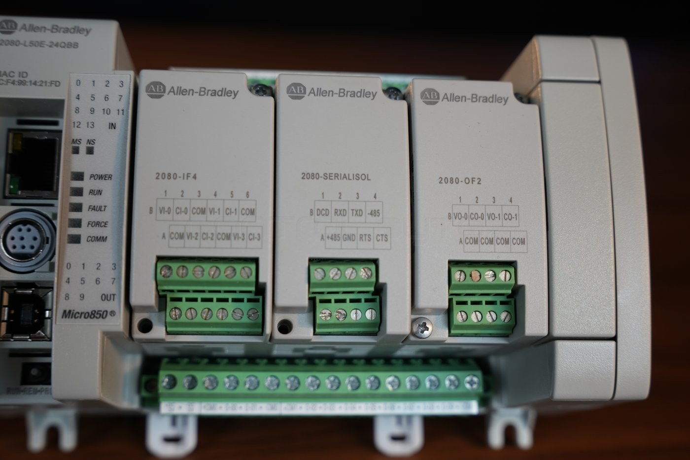
The 2080-IF4 module adds 4 analog input channels with 12-bit resolution. Each channel can be configured as voltage (0-10 V) or current (0-20 mA), which is reflected in the dual terminal labeling: VI-0 to VI-3 for voltage inputs and CI-0 to CI-3 for current inputs, with shared COM terminals. This is the module for reading analog sensors - temperature, pressure, level or 4-20 mA transmitters.
2080-OF2: two analog outputs
The 2080-OF2 is the mirror image of the input module: 2 analog output channels, also 12-bit, in a voltage (VO-0, VO-1) or current (CO-0, CO-1) variant. Such an output sets a value for a variable frequency drive, a control valve or a positioner - anywhere an actuator expects an analog signal.
2080-SERIALISOL: isolated serial port
The middle module, 2080-SERIALISOL, is a galvanically isolated serial port RS-232 / RS-485. The isolation protects the controller from potential differences and noise on long communication lines. On the terminal block you will find the RS-232 signals (DCD, RXD, TXD, RTS, CTS, GND) and RS-485 signals (+485, -485). Among other things, the module supports Modbus RTU (master and slave), which lets you connect the Micro850 to a network of energy meters, drives or operator panels.
Diagnostics: status LEDs and ports
The front of the controller is also a diagnostic panel. The set of POWER, RUN, FAULT, FORCE and COMM LEDs shows at a glance whether the controller is powered, running the program, reporting a fault, has forced I/O or is communicating. Separate MS and NS LEDs (Module Status and Network Status) describe the state of the module and the EtherNet/IP network.
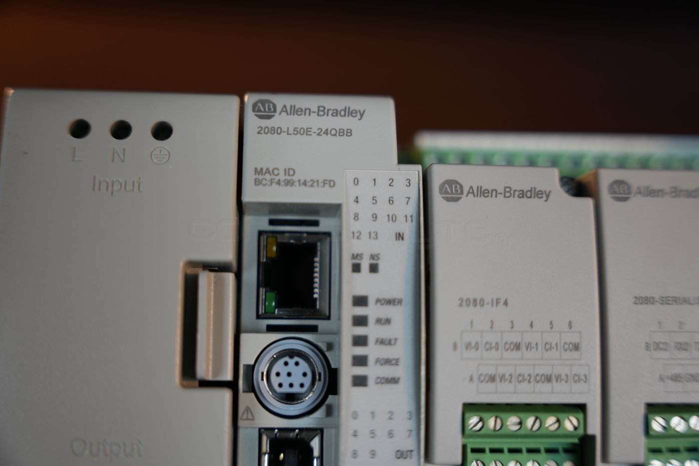
Above the LEDs you will find the RJ45 EtherNet/IP connector with its own MAC address printed on the housing, the serial port connector and the USB programming port. A built-in legend numbers the inputs (IN 0-13) and outputs (OUT 0-9), which makes wiring easier to follow. If you want to see how the Micro800 family fits alongside the larger controllers, see our overview of Allen-Bradley controllers: CompactLogix, ControlLogix and Micro800.
Assembling the set step by step
Putting such a set together into a working system comes down to a few ordered steps.
- Mount the DIN rail and snap onto it, one by one, the power supply, the controller and the expansion cap, pressing the assembly together so the bus connectors engage.
- Insert the plug-in modules into the slots on the front of the controller - in our case 2080-IF4, 2080-SERIALISOL and 2080-OF2. The controller detects them automatically once configured in the project.
- Connect the mains voltage to the L, N and ground terminals of the power supply (a step for a trained installer).
- Run 24 V DC from the power supply output to the controller power terminals and check that the DC OK LED lights up.
- Connect the field signals to the terminal blocks: digital inputs and outputs on the controller blocks, analog and serial signals on the plug-in module blocks.
- Connect the controller to the computer with a USB or Ethernet cable and download the project from Connected Components Workbench.
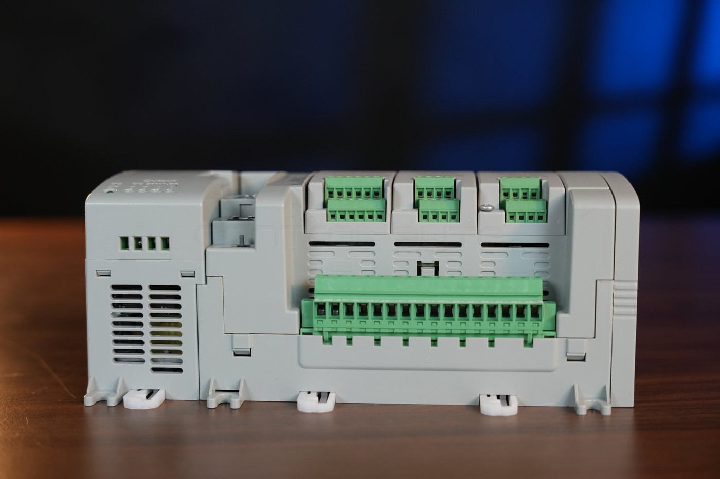
A set assembled this way is ready for lab or production work. The controller can be expanded at any time by adding 2085 expansion modules from the right side, up to a maximum of 132 I/O points.
Capabilities of the Micro850 controller
To sum up, this compact set offers a surprisingly wide range of capabilities:
- Digital control - 14 inputs and 10 outputs embedded, expandable to 132 points.
- Analog signal handling - reading 4 inputs (2080-IF4) and setting 2 outputs (2080-OF2) in both voltage and current standards.
- Industrial communication - built-in EtherNet/IP and an isolated RS-232/RS-485 serial port with Modbus RTU.
- High-speed counters - up to 4 HSC channels for encoders and pulse measurements.
- IEC 61131-3 programming - Ladder, FBD and Structured Text in the free Connected Components Workbench.
Thanks to this, the Micro850 is suitable both for simple machines and control islands and for learning PLC programming on real, industrial hardware. If you are just getting started with this family, our guide to Allen-Bradley Micro800 PLC programming for beginners is a good next step.
Frequently asked questions (FAQ)
How many modules can be connected to the Micro850 2080-L50E?
The controller has 3 plug-in slots on the front and supports up to 4 2085 expansion modules from the right side. In total this allows up to 132 I/O points.
What is the difference between a plug-in module and an expansion module?
Plug-in modules (2080 series) go into the slots on the front of the controller and do not increase the width of the system. Expansion modules (2085 series) are added from the right side on the DIN rail when you need more I/O points.
What is the Micro850 programmed in?
In the free Connected Components Workbench from Rockwell Automation, compliant with IEC 61131-3. The program is downloaded through the built-in USB port or over the EtherNet/IP network.
Does the Micro850 support Modbus?
Yes. The built-in serial port and the 2080-SERIALISOL module support Modbus RTU in master and slave mode, and the EtherNet/IP port enables communication over an Ethernet network.
Summary
The Micro850 2080-L50E is a controller that combines digital I/O, analog signals, isolated serial communication and an EtherNet/IP network in a single compact set. Such a system - power supply, CPU and plug-in modules - is a ready base for a small machine, a control island or an industrial application prototype. If you want to learn to program PLCs from scratch and put that knowledge to use in real projects, check out our premium PLC programming course in LAD/FBD. Detailed technical data for the Micro800 family can also be found in the Rockwell Automation technical documentation.
Author