The normally open contact and the coil are the two instructions you will use more than any other in ladder logic. Put one of each on a rung and you already have a working motor start circuit. In this lesson we build exactly that on a real Allen-Bradley Micro850 in Connected Components Workbench, download it to the controller over Ethernet and watch a real contactor pull in a motor. Along the way we hit the single most common confusion for beginners: a contact that is normally open in the program is not the same thing as a button with normally open contacts in the panel.
The variables we start with
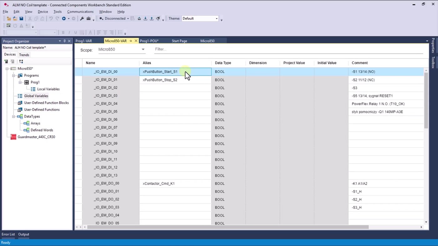
Everything begins in Global Variables. Three aliases are already defined in the project template, and their comments tell you what the physical devices are:
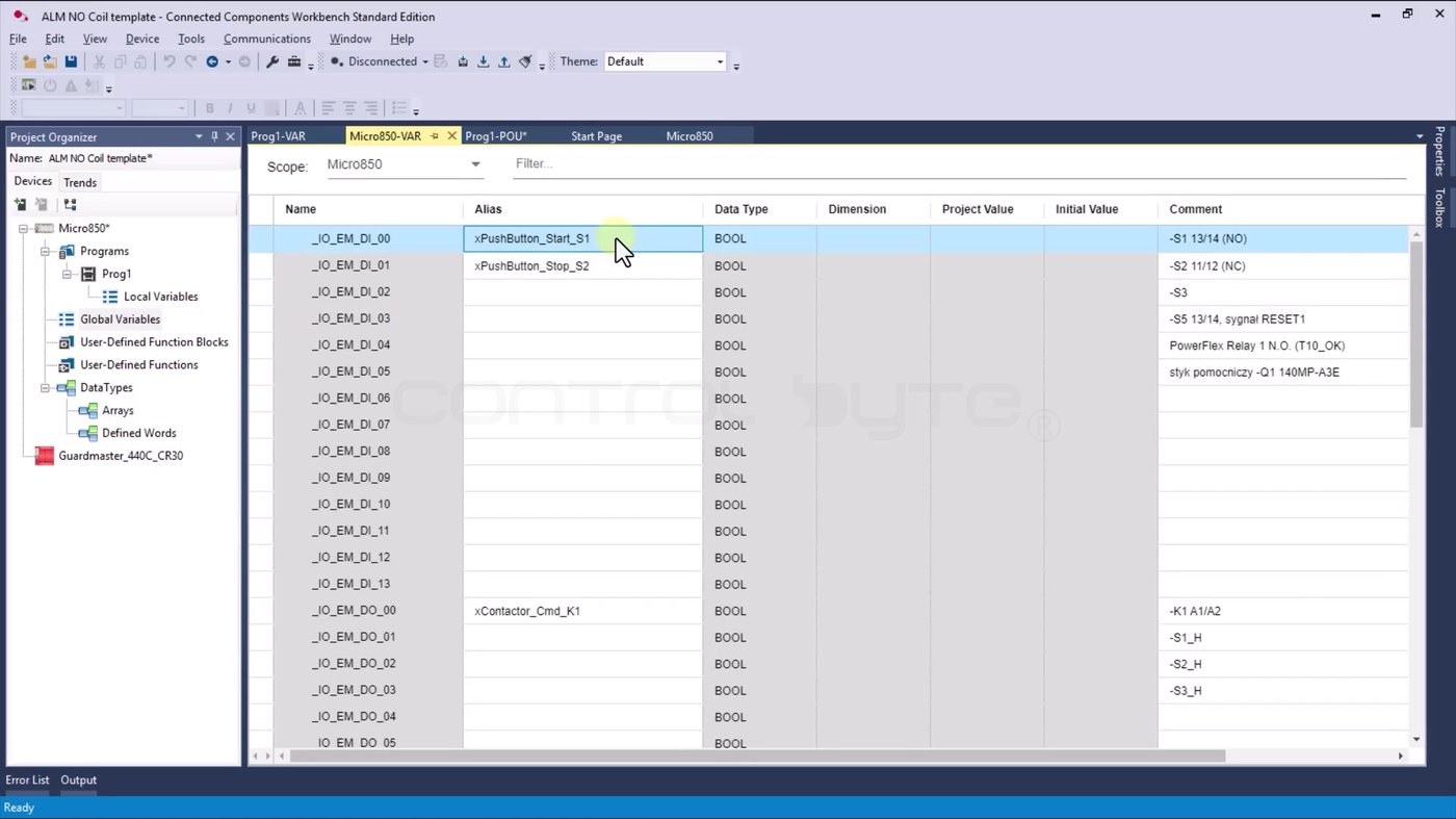
xPushButton_Start_S1on input_IO_EM_DI_00– the start button, physically S1 13/14 (NO).xPushButton_Stop_S2on input_IO_EM_DI_01– the stop button, physically S2 11/12 (NC).xContactor_Cmd_K1on output_IO_EM_DO_00– the coil of contactor K1, which switches the motor.
Note the NO and NC in those comments already. They matter later.
Building the first rung
The program has a single network, which in ladder terms is one rung. Click on the rung and insert a normally open contact, then a coil. Both show exclamation marks at first, which simply means no variable has been assigned yet.
Hover over the blue rectangle above the instruction and start typing. Connected Components Workbench filters the variable list as you type, so typing x brings up the aliases:
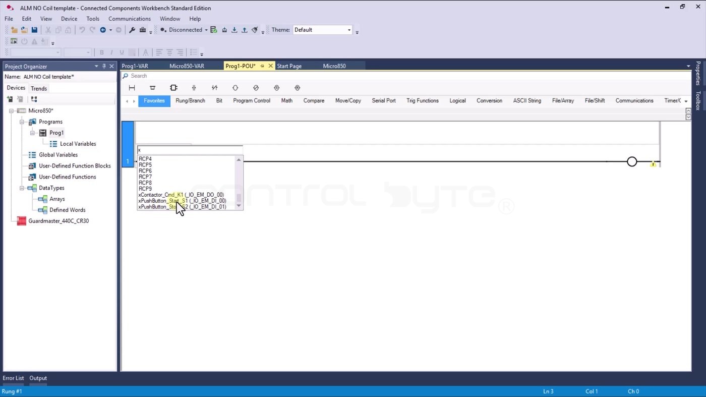
Assign xPushButton_Start_S1 to the contact and xContactor_Cmd_K1 to the coil. That is the entire program:
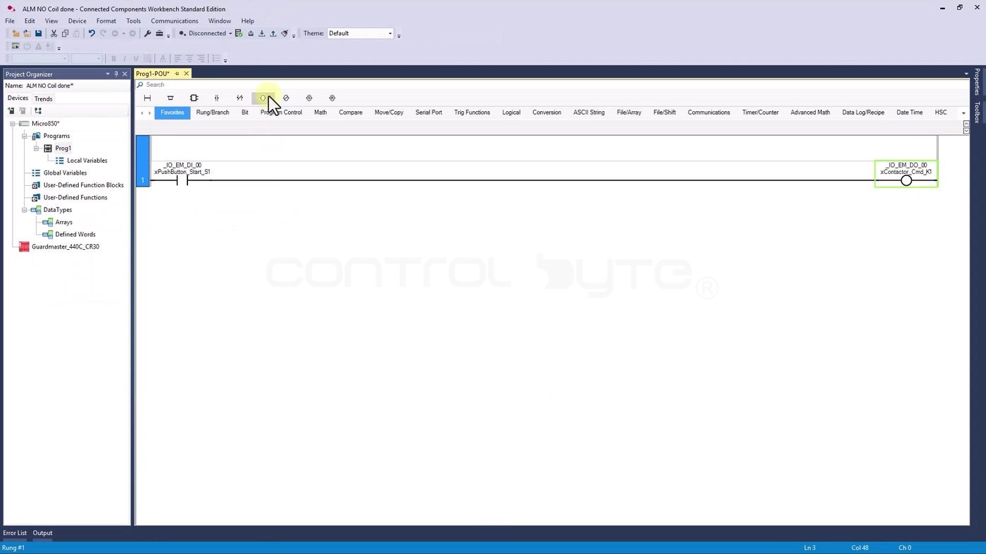
Downloading and testing on real hardware
The controller is connected over Ethernet with a static IP address, so it is just a matter of clicking download, confirming, and switching into monitoring mode.
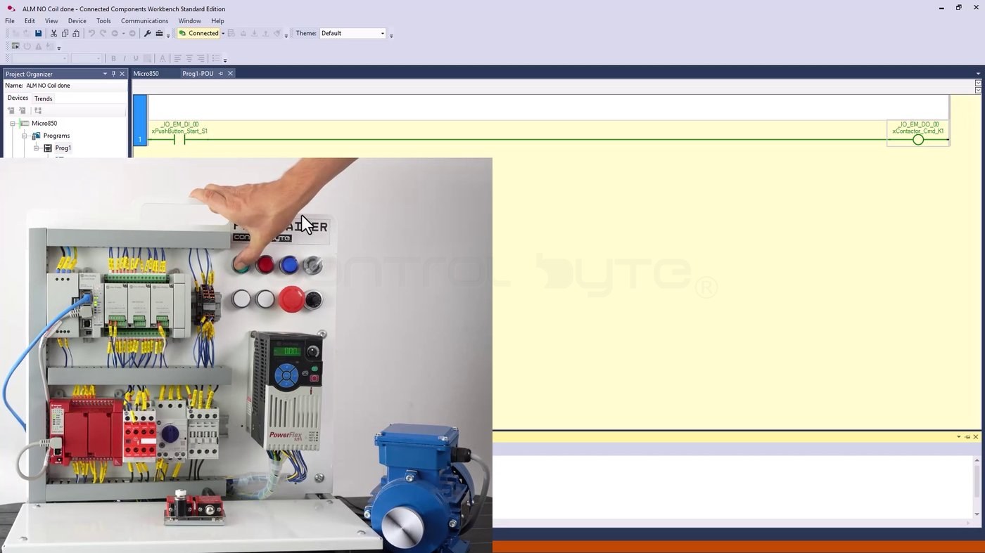
Press and hold the start button and the motor runs. Release it and the motor stops. In the monitoring view the normally open contact lights up green, which tells you a signal is reaching that PLC input, and at the same moment the controller output turns on and energizes the contactor. You can follow the same thing on the controller input and output indicator LEDs: hold start, the input LED lights, the output LED lights, the contactor pulls in.
The bench used here is our ControlByte PLC Trainer, which is why a program this small can drive an actual motor.
What a normally open contact actually does
Now the theory, which is much easier to absorb after you have seen it work:
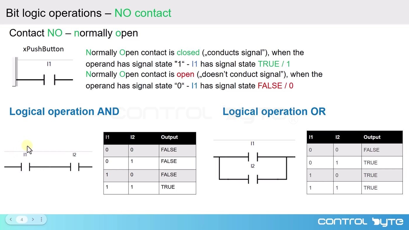
A normally open contact is closed and conducts the signal when the operand assigned to it has signal state 1 (TRUE). It stays open and does not conduct when the operand is 0 (FALSE). That is the whole rule. From it you build everything else.
AND: two contacts in series
Put two normally open contacts next to each other on the same rung, in series, and you have a logical AND. The output is TRUE only when both contacts are at 1. In practice that means you would have to press two buttons to get the motor running.
OR: two contacts in parallel
Wire two normally open contacts in parallel and you get an OR. Here a high state on just one of the contacts is enough to produce a high state at the output.
The coil: writing the result to an output
The coil is the assignment instruction. It writes the result of everything to its left on the rung into the operand you assign to it.
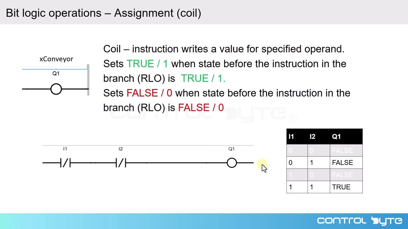
It sets the operand to TRUE / 1 when the state before the instruction on the branch (the RLO) is TRUE, and to FALSE / 0 when it is FALSE. In our circuit that operand is the contactor command, so the coil is what physically starts the motor.
Back in the program, click on the rung and add a second normally open contact, this time assigned to xPushButton_Stop_S2. You have just built an AND gate out of two normally open contacts in series – both conditions have to be met before the motor starts.
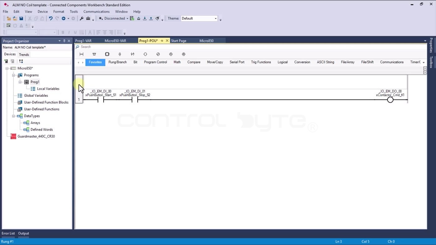
Download the modified program to the controller and test it again.
This is the part worth slowing down for.
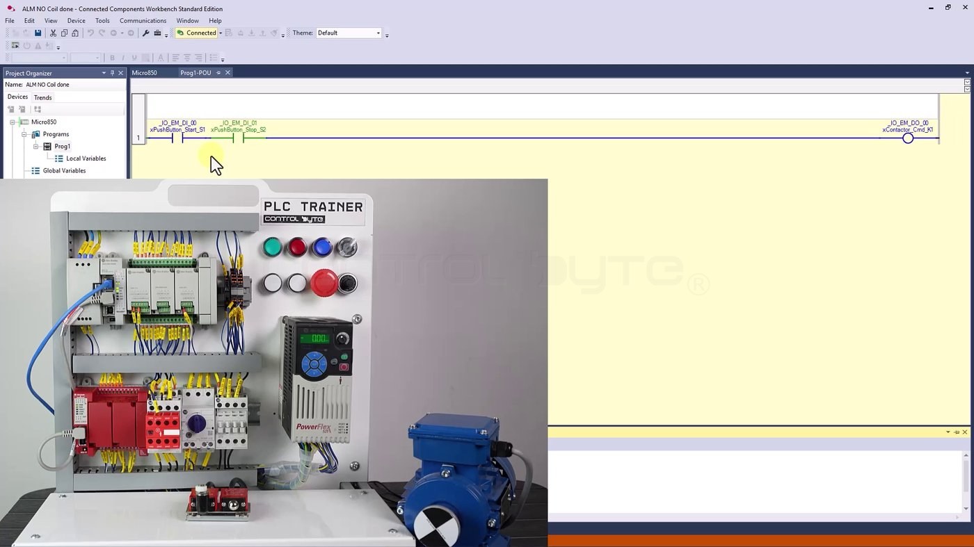
Look at the monitoring view. The stop contact is lit green even though nobody is pressing the stop button. That is because the physical stop button has normally closed contacts: at rest it is passing +24 V into the PLC input, so the input is TRUE. The start contact is highlighted blue, meaning 0 V, because the physical start button has normally open contacts and nobody is pressing it.
To drive the output you need one continuous green path across the rung. So in this circuit you have to press start, and the result is exactly what you would expect from a real machine:
- Press start: the motor runs. Release it: the motor stops.
- Press stop while holding start: the motor stops. The path is broken, there is no continuity in the program, and the contactor drops out.
- Hold stop and try to start: nothing happens. The logical condition is never met.
The motor can only be started while the stop button is feeding a high signal into the controller input – in other words, while it is not pressed. Remember the pairing: start has normally open contacts, stop has normally closed contacts, and you have to understand that from the hardware side to read the program correctly.
Frequently asked questions (FAQ)
What is a normally open contact in ladder logic?
An instruction that conducts the signal when its assigned operand is TRUE (1) and blocks it when the operand is FALSE (0). It is the basic building block used to form logic conditions on a rung.
How do I make an AND or an OR in ladder?
Put the contacts in series for AND (all must be TRUE) and in parallel for OR (any one TRUE is enough).
What does a coil do?
The coil writes the result of the rung logic (the RLO) into the operand assigned to it: TRUE when the path in front of it conducts, FALSE when it does not.
Because a real stop button uses normally closed contacts, so at rest it sends 24 V to the PLC input and the input reads TRUE. That is the safe wiring convention: if the wire breaks, the signal disappears and the machine cannot start.
Summary
One normally open contact and one coil are enough to start a motor, and two contacts in series are enough to add a stop condition. The instructions themselves are simple – the part that trips people up is that the contact symbol in the program describes the logic, while the NO or NC marking on the button describes the hardware. Read both together and the rung stops being abstract.
If you want to keep going with this controller family, see our guide to Allen-Bradley Micro800 PLC programming for beginners, and for a structured path through ladder logic take a look at our premium PLC programming course in LAD/FBD.
Author