Micro800 PLC programming is one of the easiest ways to start with Allen-Bradley controllers, because the software is free and you can run everything on a built-in simulator without any hardware. In this guide you will create your very first project in Connected Components Workbench (CCW), write your first program in Structured Text, and then build a classic ladder diagram latching circuit. Every step comes from our two short workshop videos, with a screenshot from the exact moment in each demo.
This is a beginner friendly, step-by-step tutorial. You only need the free Rockwell Automation software and the embedded Micro800 Simulator.
What is the Micro800 family and Connected Components Workbench?
The Micro800 family (Micro810, Micro820, Micro850, Micro870) is Allen-Bradley’s line of compact, low cost controllers from Rockwell Automation. They are aimed at small machines and standalone applications, and they are programmed in the free environment called Connected Components Workbench (CCW).
CCW supports the three IEC 61131-3 languages most automation engineers use every day:
- Structured Text (ST), a text based language that looks like Pascal.
- Ladder Diagram (LD), the graphical relay logic almost every PLC programmer learns first.
- Function Block Diagram (FBD), blocks wired together.
The best part for learning is the Micro800 Simulator built into CCW. It emulates a real Micro850 controller, so you can download a program and watch the inputs and outputs change without owning any hardware.
What you need before you start
You only need one free download:
- Connected Components Workbench (Standard Edition is free), version 23 is used here.
- The Micro800 Simulator, which is installed together with CCW.
No physical PLC is required. The simulator runs in RUN mode for 10 minutes at a time, which is more than enough to test the small programs in this tutorial.
You can download Connected Components Workbench and the Micro800 Simulator for free from the official Rockwell Automation website. See the Connected Components Workbench product page.
Part 1: Your first Structured Text program
In the first video we create a project from scratch and write the simplest possible program: copy one input to one output. It teaches the whole round trip, from a new project to a running program in the simulator.
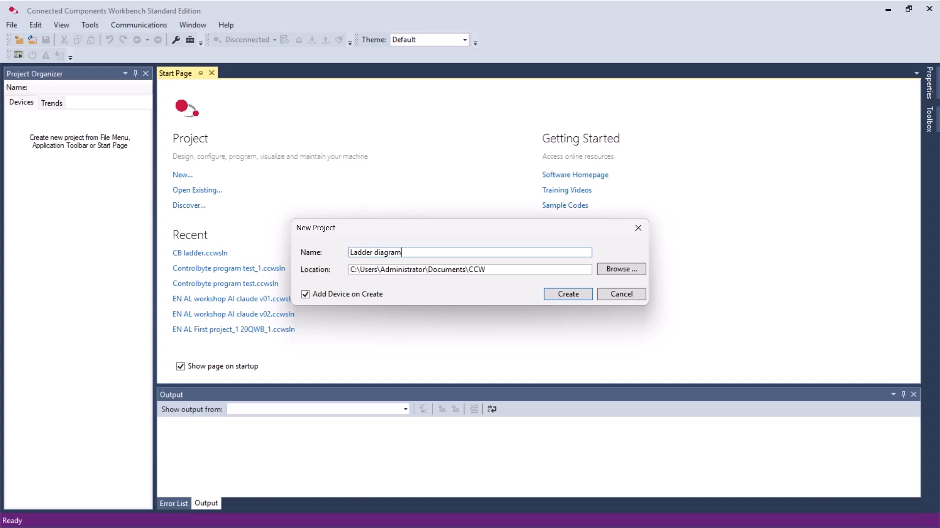
Step 1: Create a new project
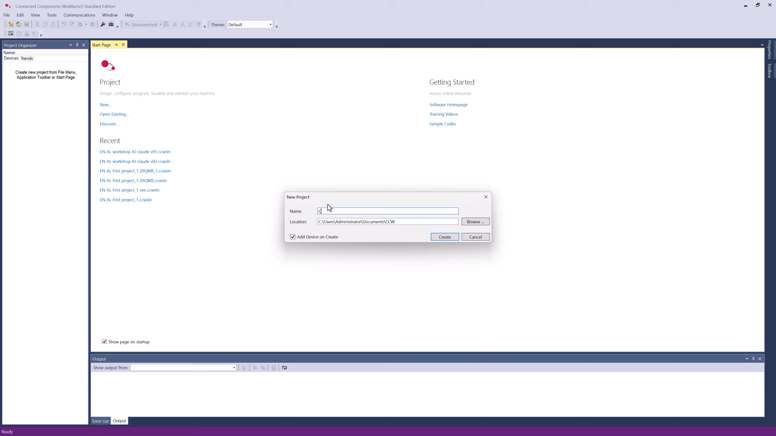
Open Connected Components Workbench and click New. Give the project a name and confirm the location, then click Create. Leave Add Device on Create checked so CCW asks you for a controller straight away.
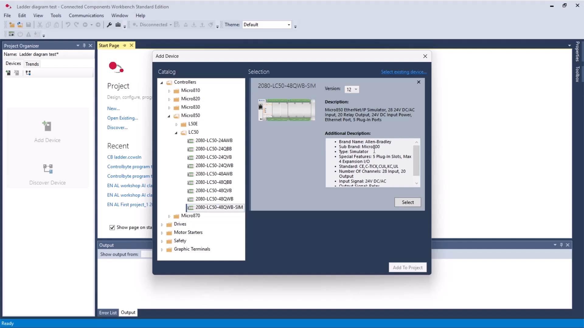
Step 2: Add a Micro850 controller from the catalog
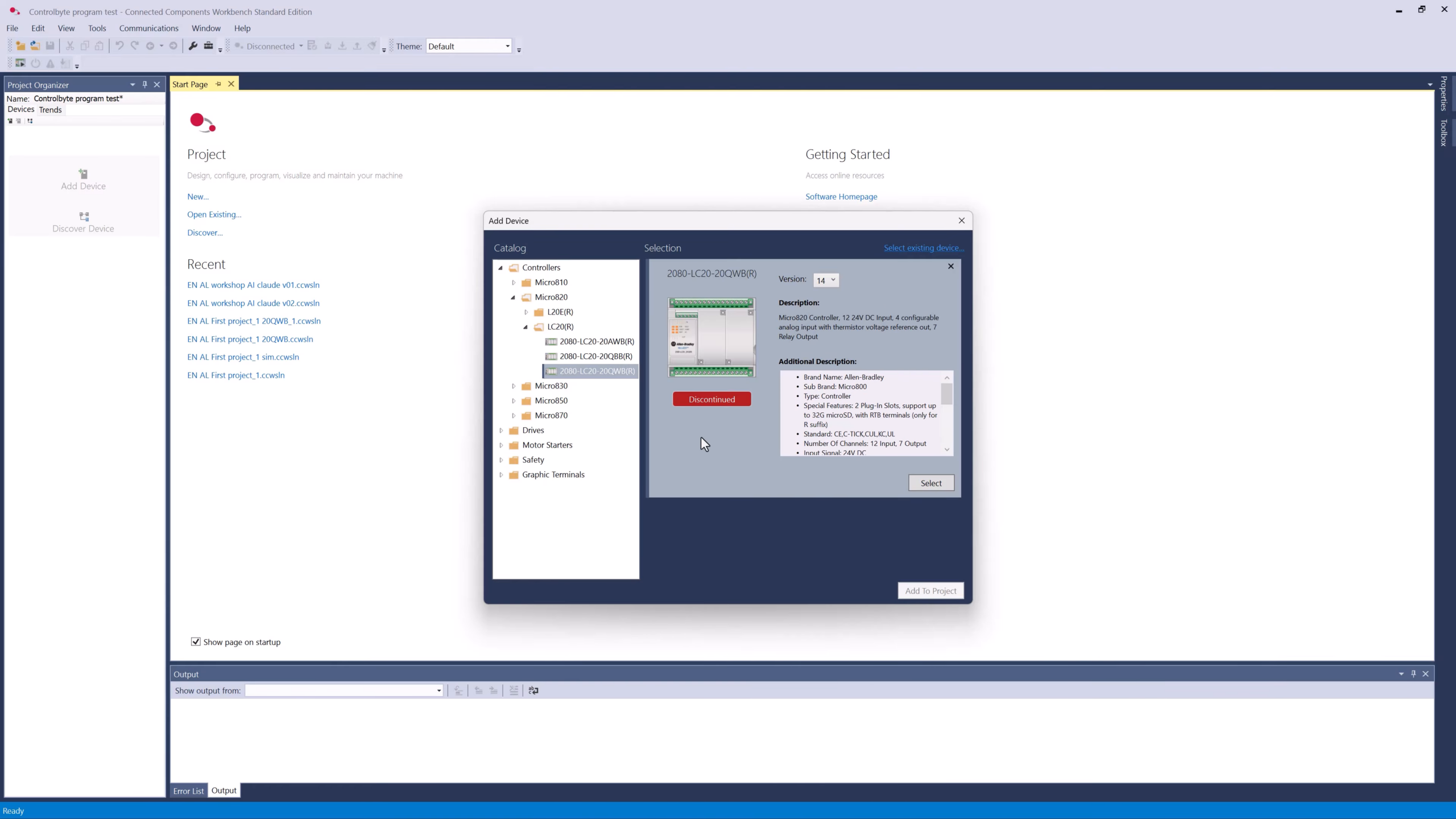
In the Add Device window expand Controllers, then the Micro850 family. Pick an active Micro850 variant (avoid the ones marked *Discontinued*). For this tutorial choose a version that matches the simulator, then click Select and Add To Project.
Step 3: Add a Structured Text program
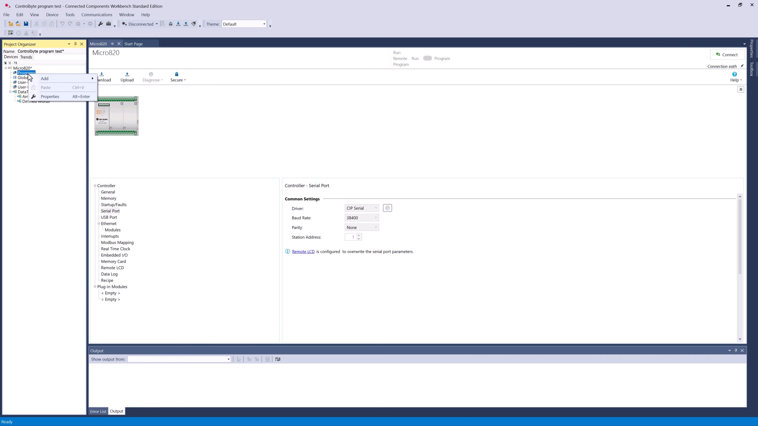
In the project tree right click on Programs, choose Add, and select a new Structured Text program. You can rename it later by right clicking the program and choosing Rename.
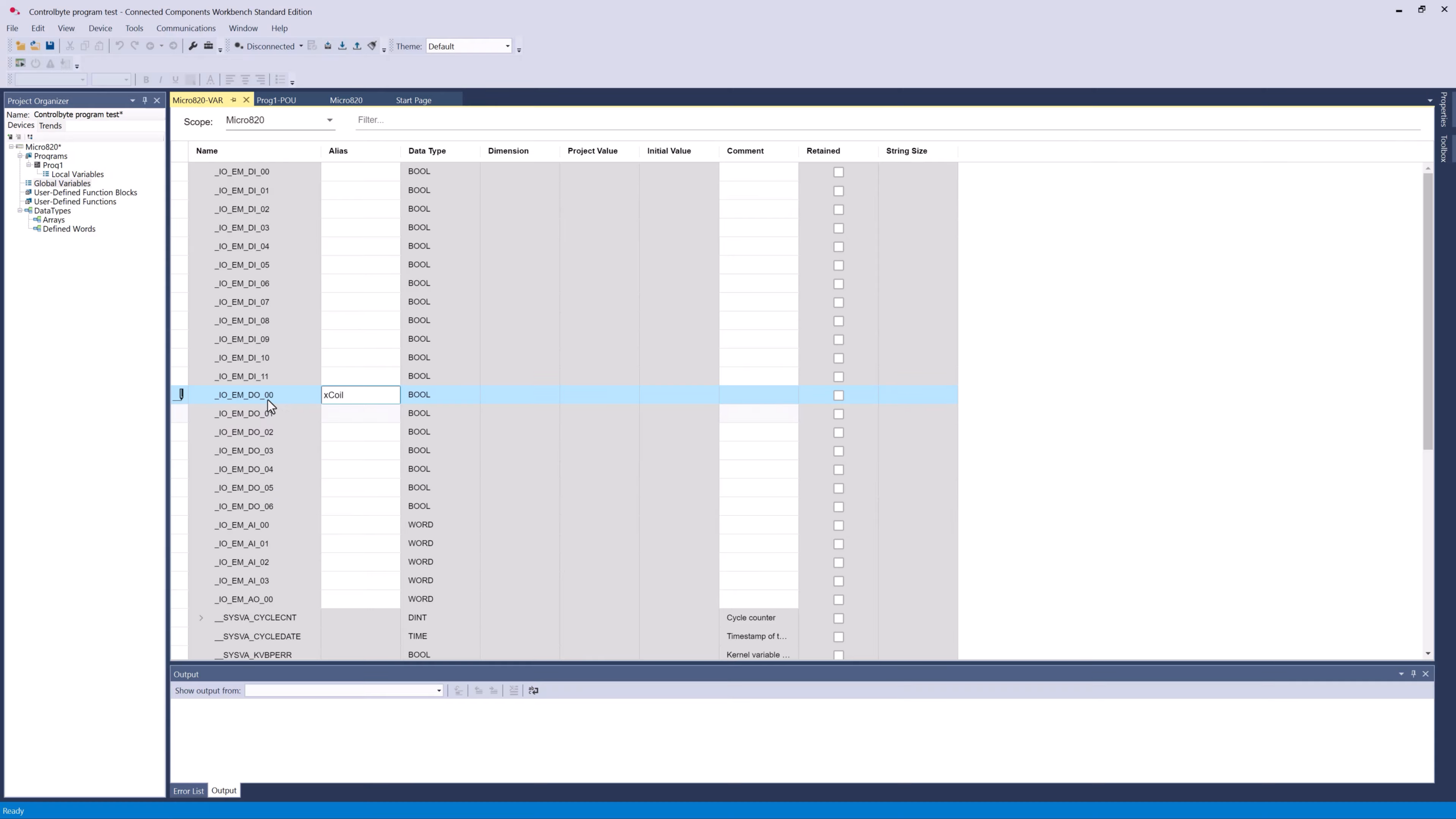
Step 4: Create aliases for your I/O
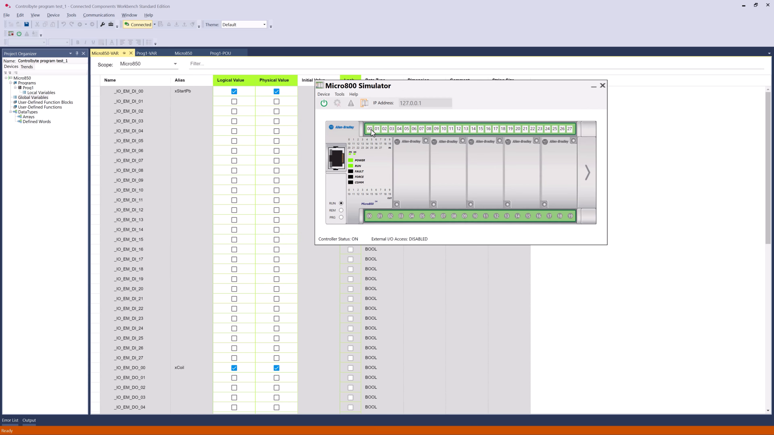
Open Local Variables, switch to the Micro850 I/O tab, and give friendly aliases to the physical channels. Here the output _IO_EM_DO_00 gets the alias xCoil and the first input _IO_EM_DI_00 becomes the start button. Aliases keep your code readable instead of full of raw channel names.
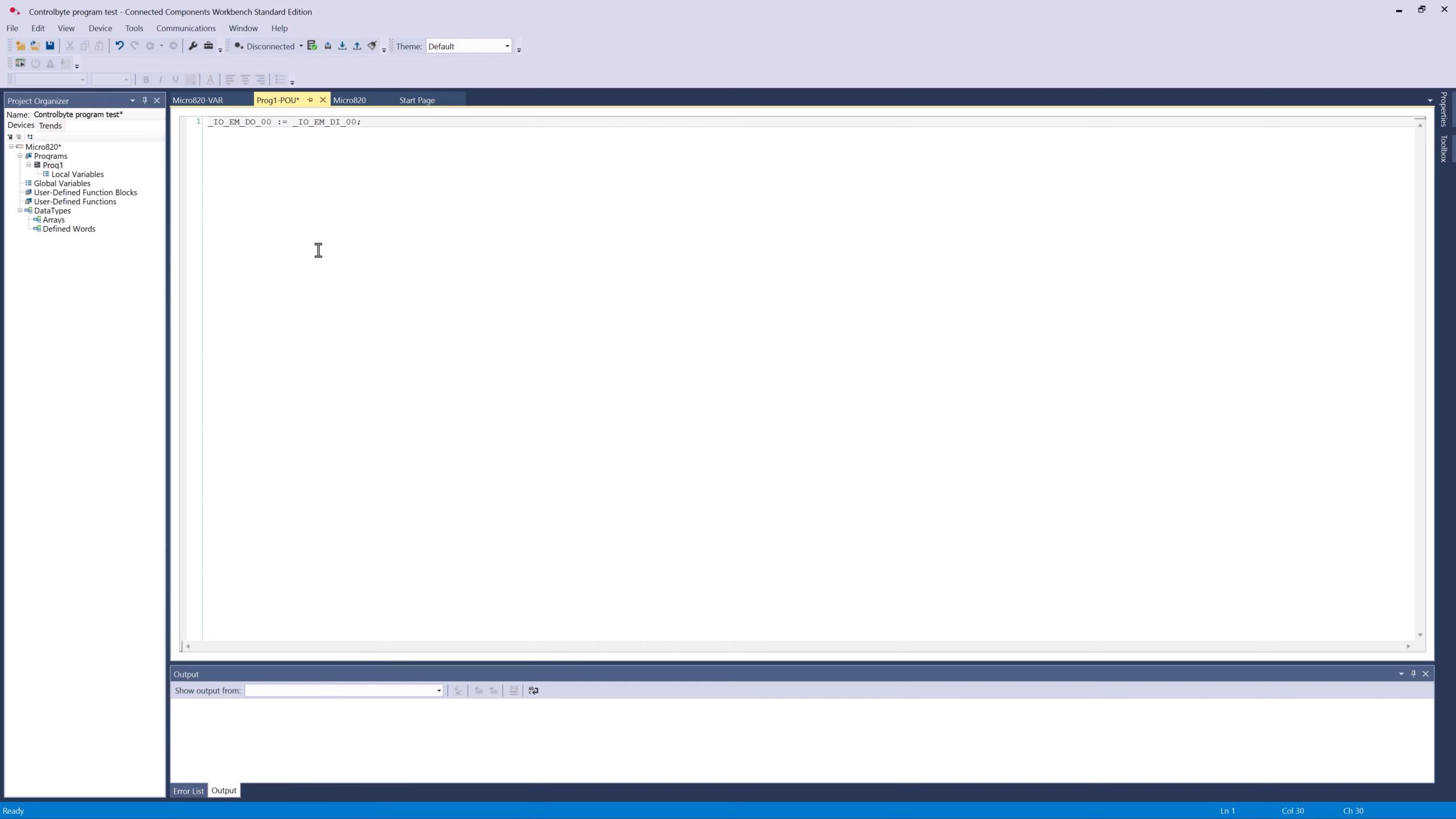
Step 5: Write the program
The whole program is a single line. In Structured Text you assign the input to the output with the assignment operator and finish with a semicolon:
_IO_EM_DO_00 := _IO_EM_DI_00;When the input is true, the output is true. That is it.
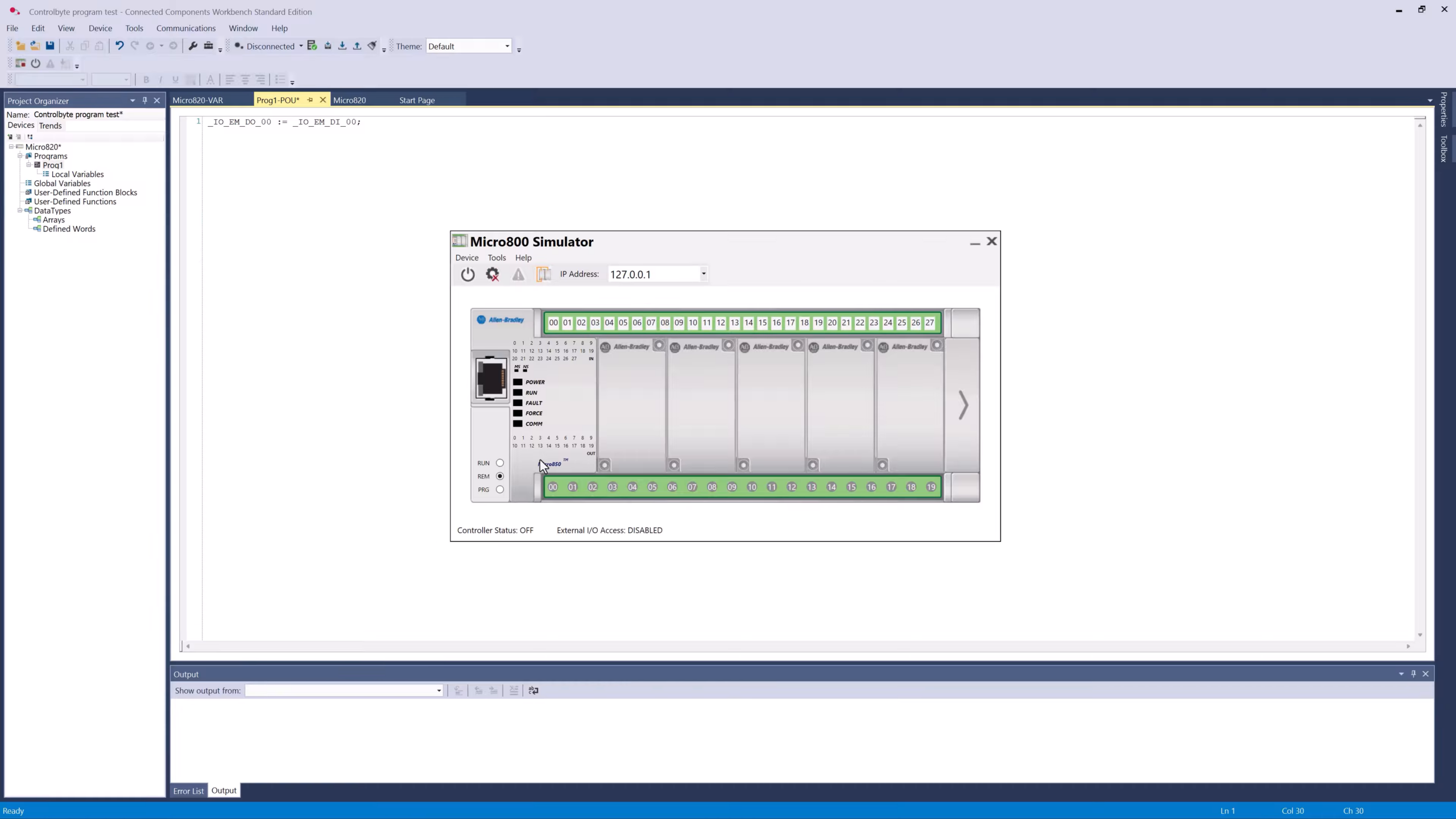
Step 6: Start the Micro800 Simulator
Open the Tools menu and start the Micro800 Simulator. It comes up with a local IP address such as 127.0.0.1. Note the controller model shown in the simulator, because it must match the controller in your project.
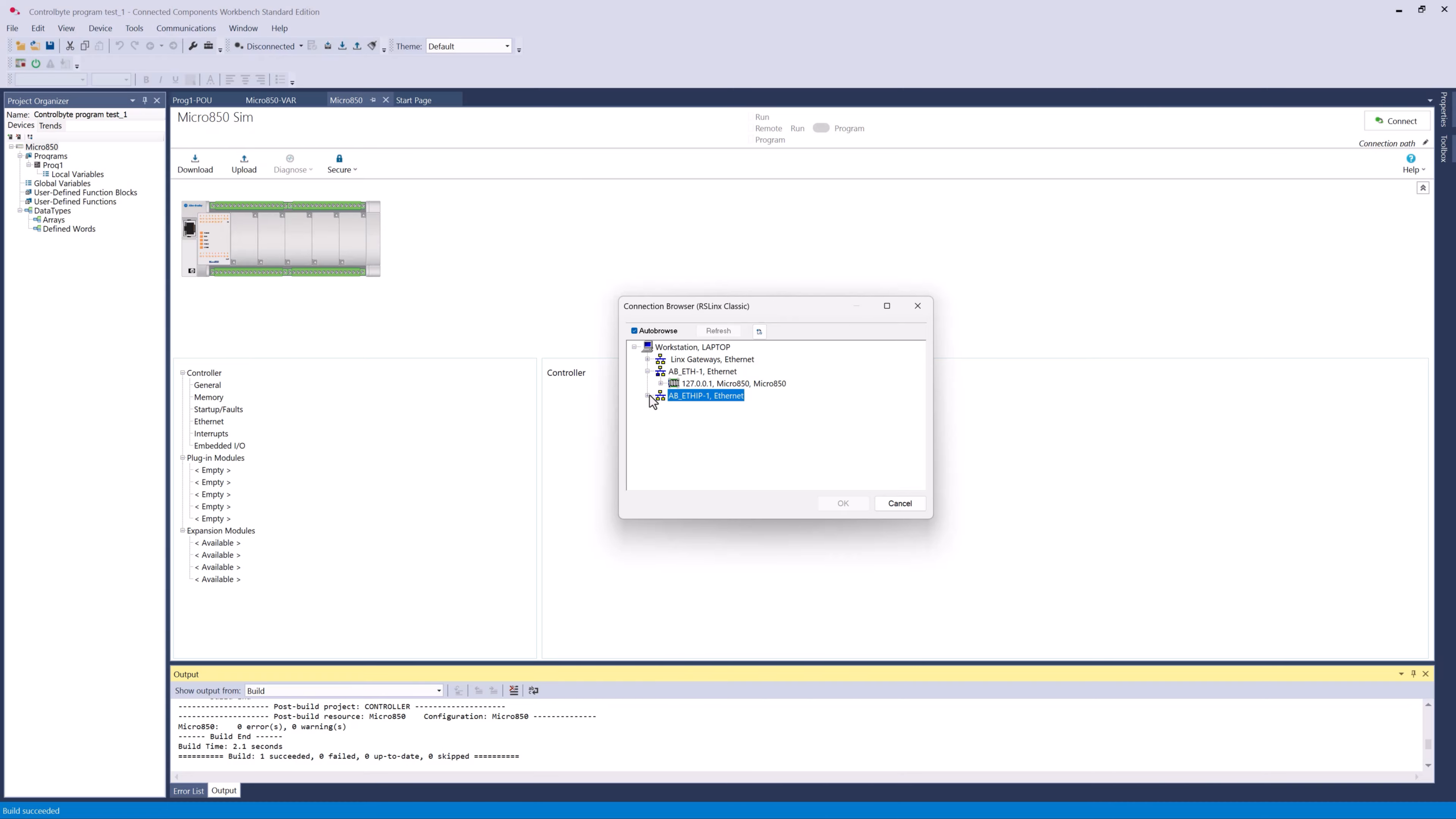
Step 7: Build, then connect through RSLinx
Build the project from the toolbox. Then open the connection path and pick the simulator in the RSLinx Classic connection browser using its IP address, and Connect. If the controller type does not match the simulator, change the controller in the project tree (right click the controller, Change Controller) and pick the simulator variant, then connect again.
Step 8: Download, run, and watch it work
Download the program to the simulated controller and switch it to RUN mode. In a Structured Text program you can monitor variable states directly. Open the simulator, toggle the first input, and the output turns on. In Local Variables you can also watch the logical and physical values change live.
Part 2: Your first ladder diagram, the latching circuit
The second video builds the most important pattern in ladder logic: the latching (seal-in) circuit that starts and keeps a motor running. This is the program every PLC programmer should know.
Step 1: New project and Micro850 simulator device
Create a new project, for example *Ladder diagram test*, and click Create. In the catalog select the Micro850 LC50 simulator variant (the one described as an EtherNet/IP simulator), then add it to the project.
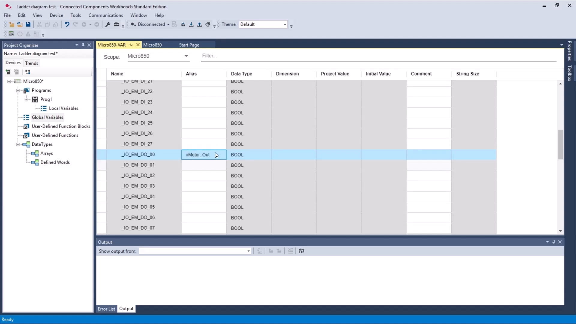
Step 2: Declare your variables
Right click Programs, choose Add, and select a new Ladder Diagram program. Open Local Variables and assign aliases using the Hungarian notation the instructor recommends, where the x prefix marks a Boolean:
xStart_PBfor the start push button (first input).xStop_PBfor the stop push button.xMotor_Outfor the motor output.
The x prefix tells you instantly that the tag is a Boolean, which only holds true or false.
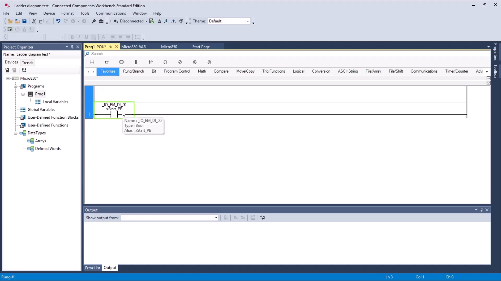
Step 3: Build the rung
On the first rung add a normally open contact for xStart_PB, then in series a contact for xStop_PB, and finish the rung with a coil assigned to xMotor_Out. Drag the elements from the toolbox and double click each one to pick its variable.
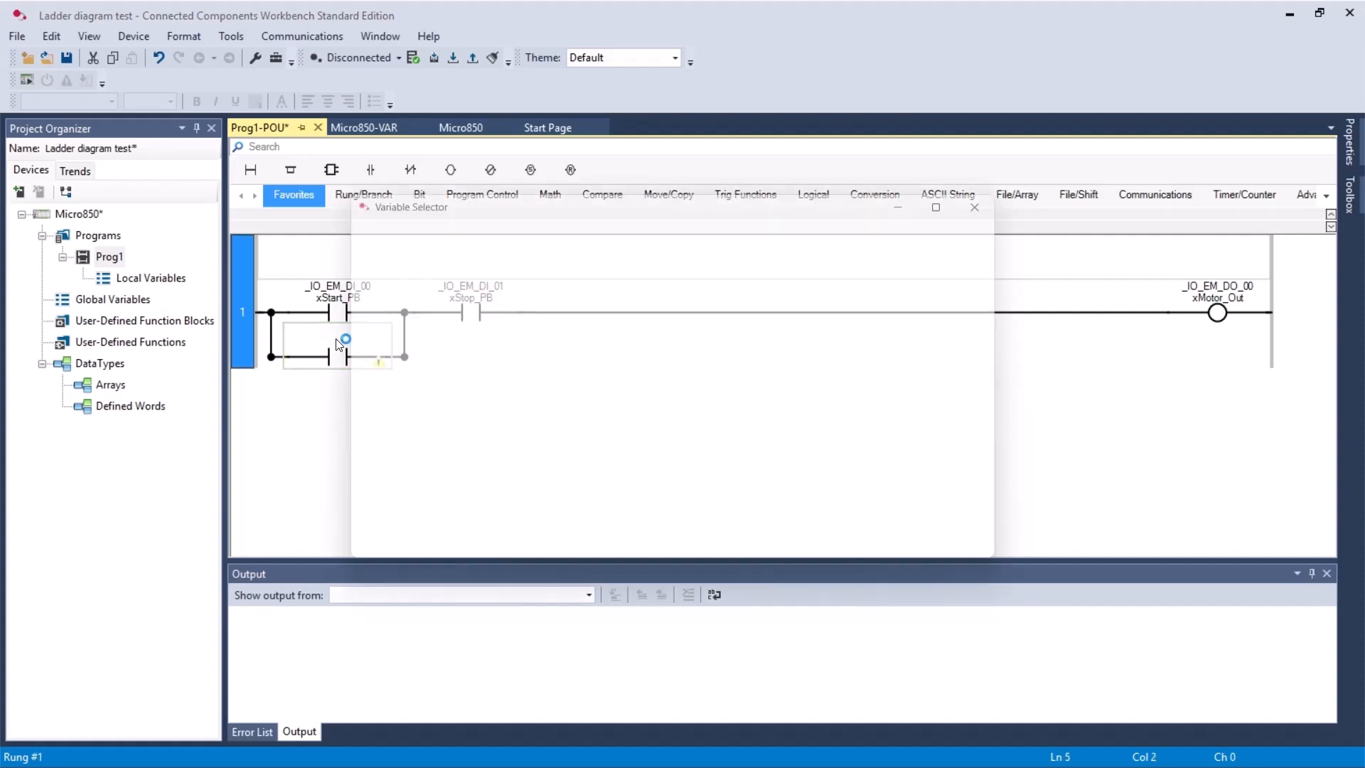
Step 4: Add the seal-in branch (the latch)
Now add a parallel branch around the start contact and drop a normally open contact of xMotor_Out into it. This is the seal-in: once the motor output is on, it keeps its own rung energized even after you release the start button. That is exactly what makes the circuit latch.
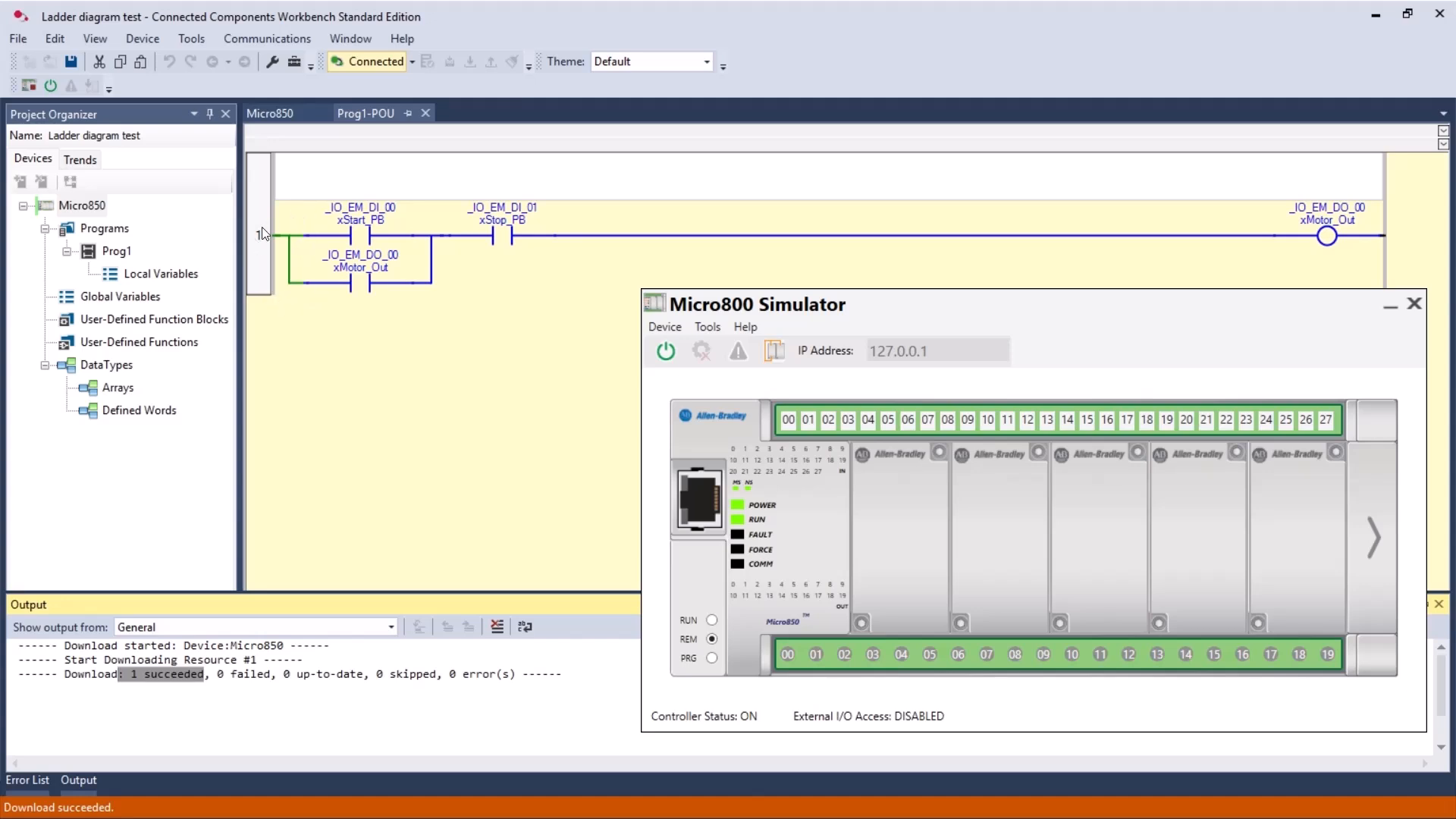
Step 5: Build, download, and run
Build the project, set the connection path to the simulator IP, Connect, and Download. Switch the controller to remote RUN (it runs for 10 minutes at a time). When the rung is live, the energized parts are highlighted in green.
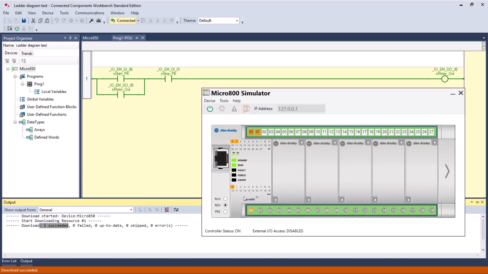
Step 6: Test the latching behavior
Because the stop button is wired as a normally closed contact, it shows green at rest. Click the start input and the motor starts immediately, and the output goes true. Release the start button and the motor keeps running, that is the latch. To stop it, press the stop button, which breaks the rung.
Structured Text vs Ladder Diagram: which should a beginner start with?
Both languages run the same Micro850 controller, so the choice is about how you think:
- Ladder Diagram is visual and maps directly to relay logic, which makes troubleshooting on a live machine very intuitive. Most beginners and maintenance teams start here.
- Structured Text is compact and powerful for math, loops, and state machines, and it scales better to large programs. It feels natural if you already know any text based language.
A practical path is to learn the latching circuit in ladder first, then rewrite the same logic in Structured Text to see how the two map onto each other.
Common beginner problems
- Connection failed: controller type does not match. The project controller and the simulator model are different. Use Change Controller in the project tree and pick the simulator variant.
- The simulator dropped out of RUN. The Micro800 Simulator only stays in RUN mode for 10 minutes, then it returns to PROGRAM mode. Just switch it back to RUN.
- A discontinued device in the catalog. Pick an active Micro850 version so you keep getting firmware and support.
- Nothing changes when I toggle inputs. Make sure you are in RUN mode and connected to the simulator, and that your aliases point to the right physical channels.
FAQ
Is Connected Components Workbench really free? Yes. The Standard Edition of CCW is a free download from Rockwell Automation, and the Micro800 Simulator is included, so you can learn Micro800 PLC programming without buying any hardware.
Do I need a physical Micro850 to follow this guide? No. Everything here runs on the built-in Micro800 Simulator. A real controller behaves the same way once you change the connection path to the hardware.
What is a latching circuit? It is a ladder pattern where the output seals itself in through a parallel contact, so a momentary start button keeps a motor running until a stop button breaks the rung.
Why use the x prefix on variable names? It is Hungarian notation. The x marks the tag as a Boolean, which makes the program easier to read at a glance.
Summary
You now know the full workflow for Micro800 PLC programming with Allen-Bradley controllers: create a project in Connected Components Workbench, choose a Micro850 controller, declare aliased I/O, write a program in Structured Text and in Ladder Diagram, and test it on the free Micro800 Simulator. With the latching circuit under your belt you have the foundation every PLC programmer builds on.
Try both programs on your own, then extend the ladder with timers and counters for a more realistic machine.
Want more?
If you are into PLC programming and industrial automation, check out our materials:
- Website: controlbyte.tech
- YouTube: ControlByte Automation