In Siemens S7-1200 and S7-1500 PLCs, timers play a crucial role. They enable precise time measurement in control programs, making them useful for signal filtering, pulse generation, delay, or signal hold functions.
This article describes the four main types of timers used in TIA Portal: TON (Timer On Delay), TOF (Timer Off Delay), TP (Pulse Timer), and TONR (Retentive On Delay).
All examples refer to S7-1200 and S7-1500 PLCs, although the timer logic remains identical for both families.
General Structure and Parameters of Timers
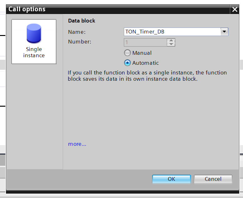
Timers in TIA Portal are implemented as IEC_TIMER structures, which are stored inside data blocks (DBs).
Each timer instance creates its own DB, allowing timers to operate independently.
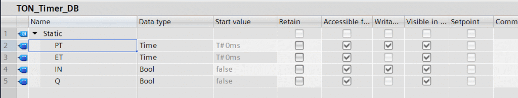
The TP, TON, TOF, and TONR instructions share similar parameters:
- IN – Boolean input signal. Depending on the timer type, a signal of 1 (TRUE) or 0 (FALSE) starts or stops time counting.
- In TP, TON, and TONR timers, a rising signal (1) starts counting, while 0 stops it.
- In the TOF timer, the behavior is reversed.
- R – Reset input (Bool), available only in TONR. A signal of 1 resets the accumulated time and sets output Q to 0.
- PT – Preset Time (TIME). Defines how long the timer should run before Q changes state. The value is entered as T#<time> (e.g., T#5s) and internally stored as a 32-bit DInt value in milliseconds.
Changing PT during timing does not affect TP, TON, or TOF timers. For TONR, the new preset takes effect at the next start. - Q – Logical output (Bool). Indicates whether the preset time has elapsed. It can be used in further logic or for visualization purposes.
- ET – Elapsed Time (TIME). Displays the current elapsed time in milliseconds.
⚙️ Each IEC_TIMER structure should be assigned to only one timer to avoid unwanted interactions.
When programming in LAD, timer instructions should be placed at the end of the network, and it is recommended to use tag outputs (Q, ET) instead of directly accessing DB variables.
How the TON Timers in TIA Portal Works – On-Delay Timer
Principle of Operation
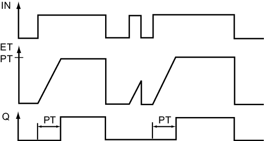
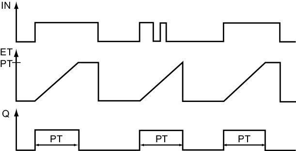
TON is the most commonly used timer in PLC programming. Timing starts when the input signal IN changes from 0 to 1.
If IN returns to 0 during timing, the timer is reset — both accumulated time and output Q return to 0 (ET = 0, Q = 0).
When ET reaches the preset time PT, output Q switches to 1. As long as IN remains high, Q also stays at 1. Once IN goes low again, the timer resets.
Typical Applications
Delayed signal activation is useful for:
- Filtering short pulses
- Soft-starting devices
- Delaying motor start after a start signal
- Ignoring short disturbances (e.g., button press must last longer than T#200ms to be accepted)
- Triggering actions after a defined delay
How the TOF Timers in TIA Portal Works – Off-Delay Timer
Principle of Operation
The TOF timer works opposite to TON. When the signal at IN changes from 1 to 0, the timer starts counting the preset time PT.
At that moment, output Q immediately switches to 1 and stays active during the countdown. After the preset time expires, Q returns to 0.
If IN goes back to 1 during counting, the timer resets instantly, and Q switches to 0.
Typical Applications
The TOF timer is used when a signal or device must remain active for a while after the control signal is removed, such as:
- A fan running for 30 s after being switched off
- Lighting turning off with a delay after motion sensor deactivation
- A valve remaining open for a defined period after signal loss
How the TP Timers in TIA Portal Works – Pulse Timer
Principle of Operation
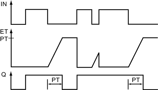
The TP timer generates a pulse of fixed duration. Timing begins on the rising edge of IN (transition from 0 to 1).
When triggered, Q switches to 1 and remains in that state for the preset time PT.
Further changes at IN during the pulse are ignored and do not extend the timing period.
After PT elapses, Q automatically resets to 0. Changing PT while the timer is active has no effect on the ongoing pulse.
Typical Applications
TP timers are useful when you need to generate a short, fixed-length pulse, regardless of input duration, for example:
- Turning on an indicator lamp for 1 s after a button press
- Generating a one-shot start pulse for a drive
- Debouncing sensors or pushbuttons
How the TONR Timers in TIA Portal Works – Retentive On-Delay Timer
Principle of Operation
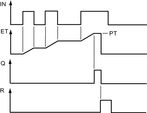
The TONR timer behaves similarly to TON but retains the elapsed time even after the input signal is turned off.
When IN = 1, the timer starts counting toward PT.
If IN goes back to 0 before PT elapses, counting pauses, but the elapsed time ET is stored.
When IN is set to 1 again, timing resumes from where it left off.
The timer resets only when R = 1.
Changing PT during timing does not affect the current cycle, but the new value is applied at the next start.
Typical Applications
Retentive timing is useful when total active time needs to be accumulated, such as:
- Recording total operating time of motors or pumps (hour meter)
- Measuring duration of alarms or limit violations
- Implementing interrupted delay sequences — timer continues after condition returns
Summary
Timers in Siemens PLCs are powerful tools for time-based logic.
Understanding the behavior of TON, TOF, TP, and TONR allows you to create more reliable, stable, and flexible automation programs in TIA Portal.
If you want to learn more about PLC programming and timers in TIA Portal, check out our Premium Siemens S7-1200/1500 Programming course with certificate and teacher’s support.