In this article, I would like to introduce you to the possibilities and advantages of the graphical LAD language for PLC programming.
This language should be your first choice if you are serious about a career in automation and project delivery. Most of the main programs for industrial machines are programmed in this language!
Learning LADDER logic is a breeze, and with just a bit of spare time, anyone can master it.
Why choose the LADDER logic to start with?
One of the best graphical programming languages for PLC programming is called Ladder Logic or Ladder Diagram (LAD).
The undoubted advantage in ladder logic is that it is more intuitive than most programming languages, so people often find it much easier to learn.
Ladder logic looks very similar to an electrical diagram with relays. If you already know a bit about relay control and electrical circuits, you can learn ladder logic even faster.
It’s not a requirement, and I myself didn’t understand relays when I first learned ladder logic.
You will probably ask:
“Can I program without having a PLC? How to learn programming without hardware?
You’ve come to the right place!
Our mission is to provide knowledge about PLC programming online. We have developed learning paths that allow you to learn in various types of simulators. You don’t need an actual PLC to start learning. All you need is your computer, a PLC-SIM simulator and an interactive factory simulation (Factory IO). Such a set will allow you to quickly learn the LAD language, which will give you the opportunity to find a job and dynamic career development of an automation programmer.
Let’s start!
What is LAD programming language – Ladder Logic?
Ladder Logic (also known as Ladder Diagram or LD) is a programming language used to program a PLC (Programmable Logic Controller). It is a graphical PLC programming language that expresses logical operations using symbolic notation. Ladder logic consists of rungs of logic, forming what looks like a ladder – hence the name “Ladder Logic”.
Ladder logic is mainly used for bit logic operations, although PLC analog input scaling is also possible. Even simple bit logic operations can be used in more advanced PLC and SCADA systems programming.
Ladder logic is not just a PLC programming language. It is one of the standard PLC programming languages. It simply means that ladder logic is described in the standard. This standard is called IEC 61131-3.
Introduction to the LAD language
LAD language is based on graphical representation, resembling an electrical ladder diagram, hence its name. The language allows users to design and implement control logic by using a combination of ladder rungs and symbolic representations of electrical components. LAD programming provides a visual and intuitive approach to programming, making it easier for both electrical engineers and automation specialists to create and troubleshoot control systems.
Nevertheless, the name itself is quite fitting because when examining the structure of a program written in this language, one can observe similarities to an actual ladder.
Although I’m more of a futurist and don’t delve into the precise history of programming, it is likely that this language was the first created for the emerging group of professionals known as automation specialists. Initially, automation engineers stemmed from electricians, and a clever individual came up with the idea of developing a language that resembled an electrical diagram. In this field, we have the ability to construct automation systems using contactors, and we possess coils similar to those found in contactors as well. Consequently, someone who previously designed automation systems solely using contactors and electrical diagrams could easily transition to working with PLC controllers.
In addition to the PLC, someone smart had to develop a graphical programming interface for users. Do you still remember DOS? I am from the generation of the 90s and I had contact with it for a while (you could even start the game there). If you remember, you know that the GUI in DOS was very poor, but it was there that the first programming systems for the PLC were created, which is why the characters that were available on the keyboard were used – dashes, brackets, dashes, etc. This was enough to graphically represent the NO contact, the NC contact, the coil, the timer and the rest of the basic elements.
If you open modern PLC programming software, e.g. Codesys 3.5 or TiA Portal, you will notice that this convention has remained until today.
I remember that I also started with this language and it was simply rewriting the input to the PLC output, i.e. actually lighting the diode with a button. I remember this incredible joy when I lifted the switch and the diode lit up, and after modifying the program it began to flicker. Anyway, the Ladder language must be known by every automation, no matter if it is old or new – that’s where you should start.
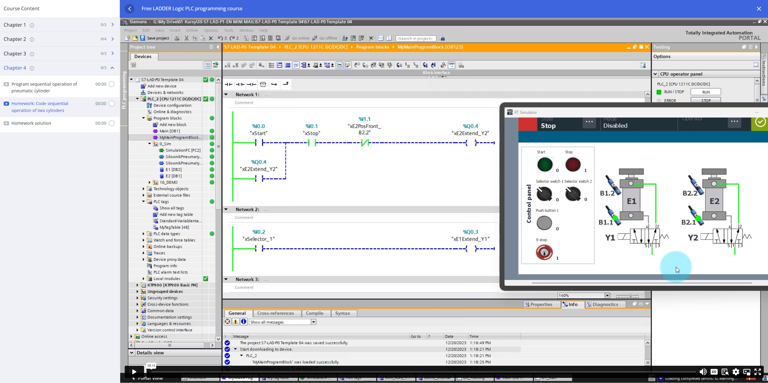
In the Ladder language, the program is divided into so-called Networks, i.e. program lines that are numbered. This is a very convenient solution because we can divide the program into sections – it is much easier to analyze such a structure during the service of a machine.
Interesting fact: the largest Ladder program I’ve come across had 1200 Networks and wasn’t divided into subroutines. It was a machine imported from Asia – there they especially liked the Ladder language. In Europe there is a slightly different approach – programs are divided into function blocks, functions, subprograms – in my opinion it is more clear.
The difference between ladder logic diagrams and electrical diagrams is how they are drawn. Electrical diagrams are often drawn horizontally, ladder logic diagrams are drawn vertically.
The best explanations for drawing ladder logic vertically instead of horizontally are as follows:
- LAD is readable
First of all, it makes ladder logic easier to read because it is natural for the eye to look from left to right and then down to the next line. As you read. Of course, this only applies to people who live in countries that read from left to right (in Japan, comic books are read backwards) - LAD is drawn on the computer screen
When you draw ladder logic on a computer, you’re making one line at a time. As you draw more and more lines (called rungs in ladder logic), they will stack on top of each other to form what looks like a ladder. The best way to look at a large ladder diagram with many lines is to scroll vertically with the screen. - The order of execution of the statement
The final reason for drawing ladder logic vertically is to determine the execution order. The execution order determines how the PLC will handle ladder logic. To be more precise, in what order the ladder logic instructions will be executed by the PLC. The PLC always starts at the top of the ladder logic and then makes its way down.

How to learn LAD programming in a month?
Now watch out! I have some clear tips for you on how to learn PLC programming from scratch without using hardware. It’s not worth wasting time and choosing what works. In my opinion, at the beginning you need to choose your mentor (an experienced colleague), who cut his teeth on automation. Where to look for such people? Most often, such people will be at your company, but you have to get there first. Therefore, there is another option. Learn from experts online through online courses. In this way, you will save time, which will translate into quick results!
Start programming in the simulator today! You don’t need expensive hardware to write simple LAD programs. You can learn everything in just a moment after installing the appropriate tools on your computer. What projects to start with? See for yourself in the next paragraphs.
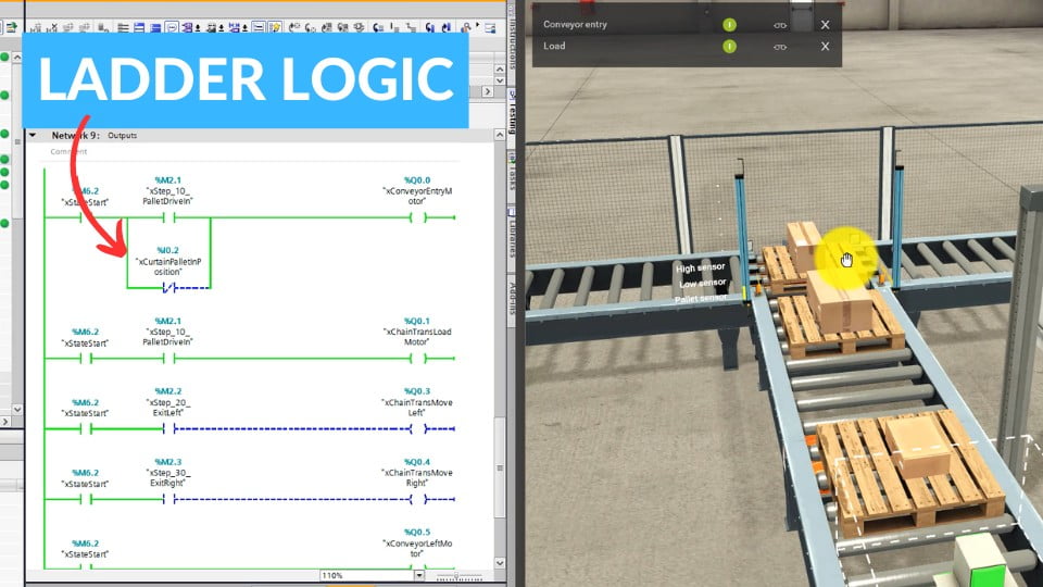
1. Pallet measurement and distribution
In this short post, I want to focus on simple projects that you can quickly implement by learning the LAD logic. The first example is a system consisting of three conveyors, which is responsible for measuring the height of packages on a pallet and their distribution. Appropriate sensors and a separating feeder are used for this. It may seem like a simple machine, but you need to know the principles of sequence design here.
Use the SET and RESET coils for this purpose. Thanks to this approach, you will be able to check the transition steps to the next steps of the sequence and activate the appropriate devices on your line. The LAD language gives the possibility of dividing the program into networks, which in turn gives an ordered structure of the project. In separate networks, you support the START/STOP/PAUSE system, manual and automatic modes and alarms.
The project is made in the free version of the Factory I/O software for 3D factory simulation. The software enables communication with the PLC simulator for Siemens controllers – TiA Portal. Just call the appropriate function block and transfer specific variables. The completed project will give you incredible satisfaction and the feeling that you can use the LAD language in real projects.

2. Product sorting line
Another object often found in factories are product sorting lines. In this type of exercise, you will learn how to use the LAD language to support the vision sensor and support individual sorters. Every automation engineer needs to know what the control box looks like. It is on it that you can mount various types of buttons, setting units and displays. You will learn about the construction of the box in the simulator and find out what signals your PLC processes.
The simplest LAD program consists of a normally open contact -| |- and -( )- coils. However, if you want to test the operation of such a program, you should refer to the signals from the inputs/outputs of the PLC. For example: you are referring to the signal taken from the START button. If this button is pressed, you start the feeder connected to the PLC output.
Such basics are enough to develop the logic of the program! All you really need is contacts and coils and the functions and function blocks you know. In the sorter design, an important function is IN_RANGE, which checks whether a given product is in the right range. Product reading is carried out by a vision sensor. To sum up, the basics of the LAD language will give you a quick effect in the form of another completed project that you can show off in your CV or show to your boss when talking about a raise.

3. Proportional regulator for liquid tank
In addition to writing sequences for machines, the LAD language is great for handling industrial processes. One of the interesting programs is to write a simple PI controller to control the liquid level in the tank. You will recalculate the values from the level sensors and for the setpoints, and then you will tune the PI controller accordingly.
In this exercise, knowledge of analog measurements is added. In LAD, processing these values will be quick and simple. It is worth using comparison operators to enable/disable the operation of the regulator. Regulator operation scenarios may be different. For example, you need to consider the sequence of filling and emptying the tank. However, you have a tool that makes your job easier. You can program in LAD!

4. Program and HMI project for 2D manipulator
Each machine is equipped with an HMI panel. It is important that you know how to design a visualization and properly connect your LAD logic with visualization tags. My project proposal is an HMI panel for a 2D manipulator.
The station consists of two conveyors and an XY manipulator. Your task is to write a program that stacks products in a box. The manipulator takes products from one line and stacks them on top of each other. Here again, you need to think about writing a few networks in LAD to handle manual/auto modes and start/stop/pause states. Ready-made visualization templates that can be downloaded on our platform can make it easier. We use such visualizations in projects for our clients.
Remember that your goal is to write the program in such a way that the customer is happy. This usually means that you choose the language required by the facility. It must be a language that is easy to analyze for maintenance and service. Our experience shows that the LAD language is a good choice for which the client will have no objections!

It was an introductory article in which you learned what the LAD language is and what projects you can implement using the simulator. You can find a comprehensive introduction to the LAD language below in the video!
Join the full PLC Siemens programming course with ControlByte: https://controlbyte.tech/siemens-plc-training/