Dear Reader,
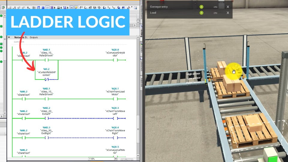
Welcome to our series on Ladder Logic (LAD) for Programmable Logic Controllers (PLC). LAD is a simple yet powerful way to program machines that are used in factories and many other places.
Our goal with these articles is to help you understand both the basic ideas and how to use LAD in real situations. We’re working with Factory IO, a tool that lets us show how machines work using simulations. This means you’ll see examples that make it easier to understand how to use LAD for different tasks. Step by step, we’ll look at different ways to use LAD, so you can see how it works in action.
If you’re new to this, don’t worry. Learning to program with LAD might seem hard at first, but it gets easier the more you try, especially when you have good examples to follow. We’re here to help guide you from the very basics to more advanced stuff. We’ll start with something simple: a project that involves a conveyor belt. This is a great place to begin if you’re new to programming.
I invite you to join me on this journey through the world of PLC programming in the ladder logic language LAD. Together, we’ll discover how just a few lines of code can control the world.
Are you ready to begin this adventure? Prepare yourself for a series of articles that will open new perspectives for you in the field of industrial automation.
Let’s start with the simplest scenario…
| Variable name | Type | Address |
| xPushButtonStart | Bool | %I0.0 |
| xPushButtonStop | Bool | %I0.1 |
| xConveyorEnable | Bool | %Q0.0 |
The first rung, Network 1, showcases an input component represented by a normally open (NO) contact labeled “%I0.0 ‘xPushButton Start'”, which correlates to a green ‘start’ button in the Factory IO simulation.
Upon actuation, this green ‘start’ button triggers the corresponding output on the same rung, denoted as “%Q0.0 ‘xConveyor Enable'”. This output is designed to activate or enable the conveyor belt within the Factory IO simulation, setting it into motion.
The ladder logic’s straightforward flow shows an immediate response from the conveyor system as soon as the green ‘start’ button is pressed. There are no intermediary steps or conditions presented between the input and the output, which illustrates a direct control relationship between the start button and the conveyor’s operation.
Scenario #2: A Latching Circuit 😃
Network 1 includes a single input contact labeled “%I0.0 ‘xPushButton Start'”, connected in series with an output coil labeled “%Q0.0 ‘xConveyor Enable'”.
The input “%I0.0 ‘xPushButton Start'” is designed to represent a green ‘start’ pushbutton in the Factory IO simulation. When this button is pressed, it closes the contact in the ladder diagram, allowing current to flow to the output coil. The output coil “%Q0.0 ‘xConveyor Enable'” then activates the conveyor belt within the simulation.
In a latching circuit, this output coil could be used to maintain the conveyor belt’s motion even after the start button is released. To achieve this, “%Q0.0 ‘xConveyor Enable'” would be connected in parallel to the “%I0.0 ‘xPushButton Start'” contact. This means that once the start button is pushed and the output coil “%Q0.0 ‘xConveyor Enable'” is energized, it will continue to allow current to flow, latching the circuit in the ‘on’ position and keeping the conveyor belt moving until another condition or input breaks the circuit. This setup is common in PLC programming to maintain states in industrial controls.
Scenario #3: A Start-Stop system with a Start Button and a Stop Button 😃
In Network 1, there are two inputs: “%I0.0 ‘xPushButton Start'” and “%I0.1 ‘xPushButton Stop'”, along with an output coil “%Q0.0 ‘xConveyor Enable'”. The ‘Start’ pushbutton, when pressed in the Factory IO simulation, energizes the output coil and initiates the conveyor belt’s operation.
After the ‘Start’ button input, there is a parallel connection to the output coil which creates a holding circuit. This means that once the ‘Start’ button is pressed and the coil is energized, the conveyor belt will continue to operate even after the button is released.
The ‘Stop’ pushbutton is connected as a normally closed (NC) contact in the physical world, which means it sends a TRUE signal when it is not pressed. However, in the ladder diagram, it is represented as a normally open (NO) contact. This is because in the logic of the diagram, the contact appears closed when the ‘Stop’ button is not pressed, allowing the holding circuit to keep the conveyor belt running. When the ‘Stop’ button is pressed, it “opens” this NO contact in the ladder logic, which actually cuts off the latching circuit, causing the output coil to de-energize and the conveyor belt to stop.
Scenario #4: A Start-Stop system with a Start Button and a Stop Button 😃 – with an SR Flip-Flop
The PLC ladder diagram in the image includes an SR (Set-Reset) flip-flop logic control block, which is employed to maintain the state of an output based on the states of two input commands.
The first input “%I0.0 ‘xPushButton Start'” is associated with the set command of the flip-flop. In a practical scenario, such as a Factory IO simulation, pressing this button would send a signal to set the flip-flop, thus energizing the output coil “%Q0.0 ‘xConveyor Enable'” and turning on the conveyor.
The second input “%I0.1 ‘xPushButton Stop'” is connected to the reset command of the flip-flop. This input is typically represented in the physical world as a normally closed (NC) button, which conducts when not pressed and breaks the circuit when pressed. In ladder logic, it’s depicted as a normally closed contact, so when the ‘Stop’ button is pressed, it sends a reset signal to the flip-flop, which de-energizes the output coil “%Q0.0 ‘xConveyor Enable'”, stopping the conveyor.
The SR flip-flop’s output is connected to the coil controlling the conveyor, ensuring that once activated by the start button, the conveyor remains on until the stop button is pressed. This setup is advantageous for applications where a process must continue without holding the start button down and should only stop when a stop command is given, providing a secure control method for starting and stopping machinery.
Scenario #5: Approach to a Sensor 😃
The first input “%I0.0 ‘xPushButton Start'” is wired to the ‘Set’ (S) input of the flip-flop. In a simulation like Factory IO, activating this button sends a signal that sets the flip-flop, thereby energizing the output coil “%Q0.0 ‘xConveyor Enable'” to start the conveyor belt.
When the ‘Stop’ pushbutton “%I0.1 ‘xPushButton Stop'” is engaged or the sensor %I0.2 ‘xSensor’ detects an object (since it’s NC, it sends a TRUE signal when the sensor’s path is clear), either condition will reset the flip-flop, which turns off the output coil “%Q0.0 ‘xConveyor Enable'”, stopping the conveyor.
What’s next?
We are working on the next part of this article series.
Meanwhile… check out our PLC Training in Ladder Logic.