Introduction
Safety (Fail-Safe) controllers are special CPU units and I/O modules that, in addition to standard automation functions, also perform tasks related to machine and process safety. Thanks to this, they can simultaneously control the machine in standard mode and monitor its safety in accordance with the requirements of PN-EN ISO 13849-1 (PL) and IEC 61508 / IEC 62061 (SIL).

Examples of applications include: emergency stop buttons (E-Stop), safety light curtains, safety interlocks, two-hand operator buttons, and speed and position control.
Fail-Safe Processors (SIMATIC S7-1200, S7-1200 G2, S7-1500, ET200SP)
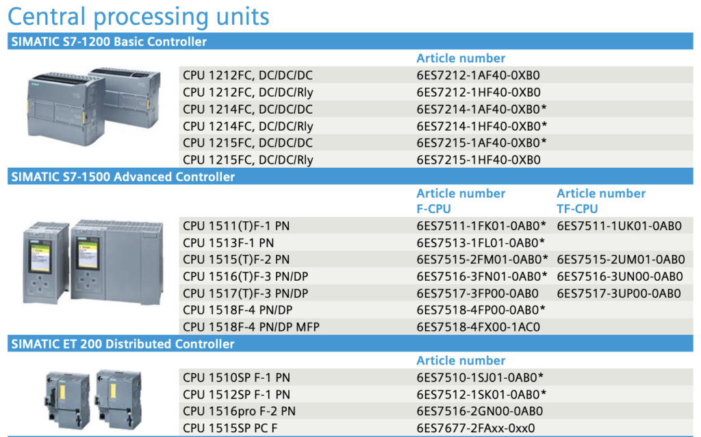
The SIMATIC family offers controllers in standard versions and in versions marked with F (Fail-Safe), such as CPU 1214FC, CPU 1516F-3 PN/DP, or CPU 1510SP F-1 PN. In addition to the standard control program, they have a dedicated Safety area where safety logic can be created.
This means that in a single CPU unit we have: a standard program (e.g., motor control, HMI panel handling) and a Safety program (e.g., response to emergency stop).
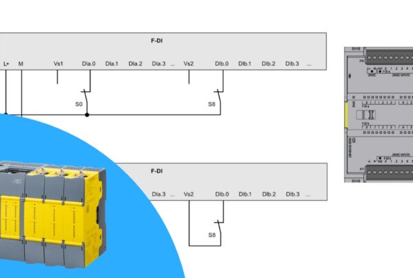
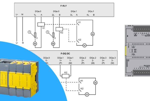
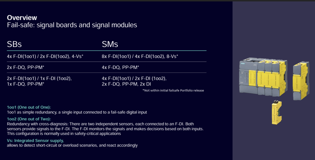
Safety I/O Modules
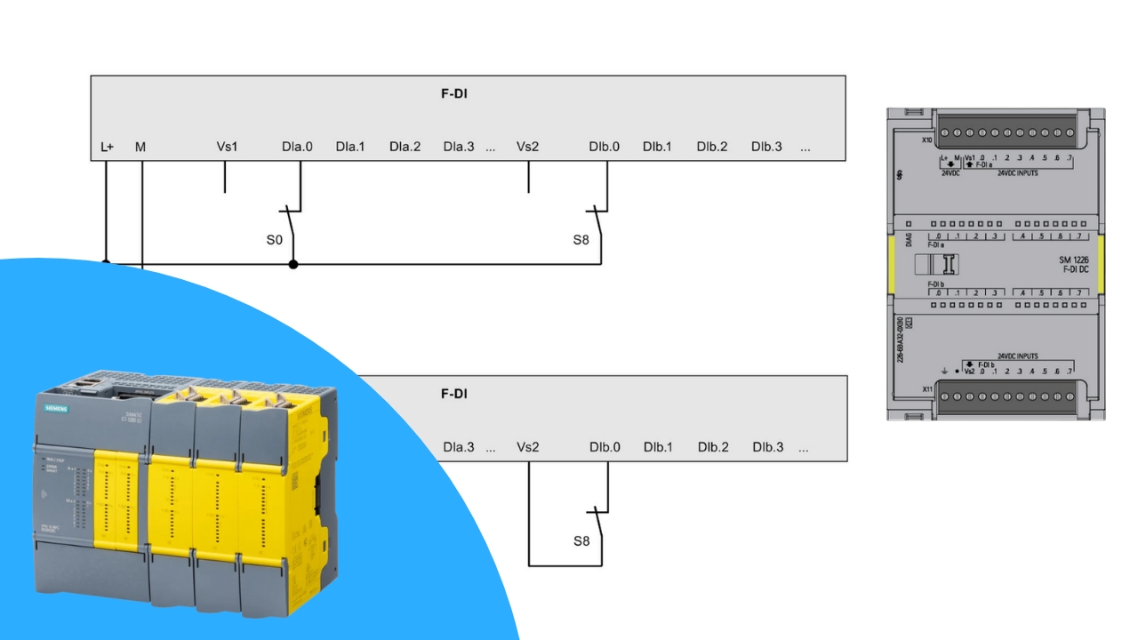
Special F-DI and F-DQ modules are connected to fail-safe processors, which differ from standard modules in that they:
- Have error detection mechanisms (e.g., short circuits, signal discrepancies)
- Communicate using the PROFIsafe protocol
- Ensure error response in the form of transitioning to a safe state (“0” = no voltage)
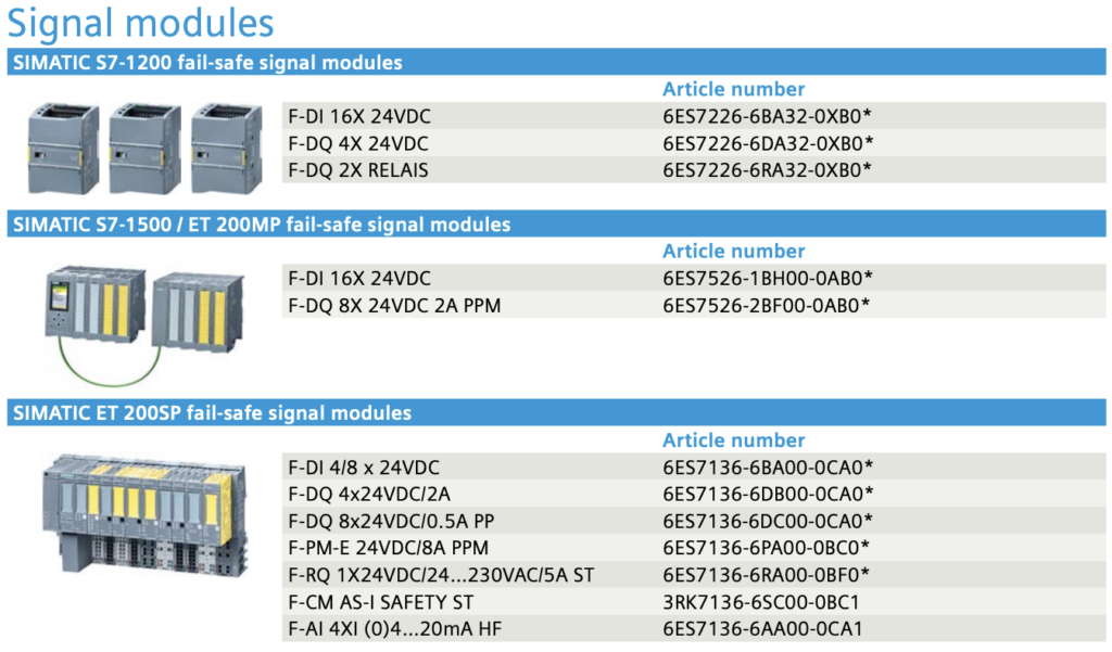
Module examples: S7-1200 SM1226 F-DI/F-DQ – safety modules for small applications, ET 200MP F-DI/F-DQ – modules for S7-1500 controllers, ET 200eco PN – distributed modules for harsh conditions.
Differences Between Standard and Fail-Safe CPU Behavior
Safety controllers have a number of additional mechanisms:
Safety Mode: activates error detection and response functions, the Safety program cannot be modified in active mode, online testing only in deactivated mode.
PROFIsafe Frame: contains process and status data, a monitoring number (keep-alive), and a CRC signature verifying data integrity.
Fault Reaction: forces a safe state (“0” – no voltage), applies to digital inputs and outputs, triggered by hardware errors, communication errors, or signal discrepancies.

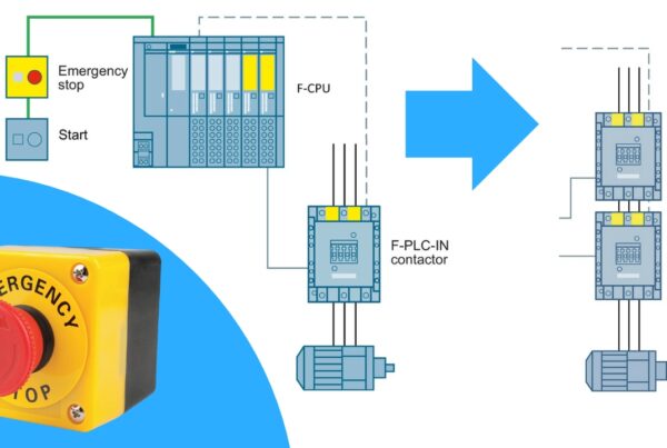
Example Application
The diagram above shows an application with CPU 1516F and a distributed ET 200SP Failsafe station. The system includes: Start/Stop buttons, an Emergency Stop button, an acknowledgment circuit (ACK), and F-DI and F-DQ modules controlling drives.

Operating principle: pressing E-Stop causes immediate shutdown of safety outputs. The controller transitions to a passive (fail-safe) state. To restart the machine, ACK confirmation and restart are required.
Summary
Safety (Fail-Safe) controllers are an essential element of modern automation systems. By integrating the standard and safety programs in a single CPU, we lower investment costs, reduce the amount of hardware (no additional safety relays), meet PL and SIL normative requirements, and ensure fast error response and simpler diagnostics. Thanks to the rich offering of CPUs and fail-safe modules, SIMATIC S7-1200, S7-1500, and ET 200 solutions can be used in both small and distributed industrial installations.
👉 Check out our full Safety PLC Course here
Want to master Safety PLC programming? Learn everything from safety principles to real-world configurations in our comprehensive online course.