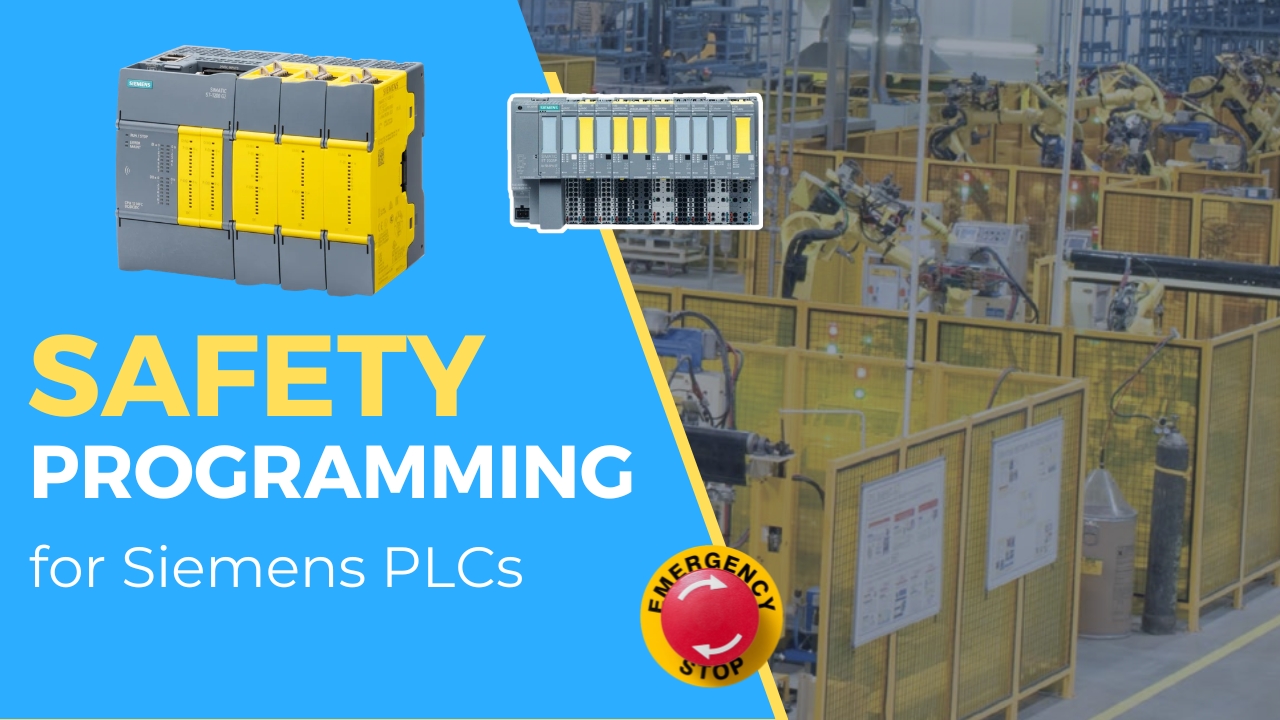
Introduction
Safety (Fail-Safe) controllers in industrial automation systems are responsible not only for monitoring input signals (emergency buttons, light curtains, interlocks) but also for safely controlling actuators – contactors, valves, and actuators. To achieve this, special safe output modules (F-DQ) are used, which guarantee that in case of an error detection, the system transitions to a safe state and disconnects power from loads.
In this article, we will cover: differences between transistor and relay outputs, F-DQ module construction and diagnostics, the most important technical parameters, practical load connection methods, and example application diagrams.
Types of Safe Outputs – Transistor and Relay
1. Transistor Outputs – SM 1226 F-DQ 4 × 24 V DC

The SM 1226 F-DQ module has four transistor channels, each designed to control a 24 V DC load with a current of up to 2.0 A.
Features: fast switching (ideal for solenoid valves or LED lamps), P+ and M– switching support, each channel built with two independent paths (P-switch and M-switch), redundancy and diagnostics at SIL 3 / PL e level.
Typical applications: hydraulic and pneumatic solenoid valves, DC contactor coils, signal lights.
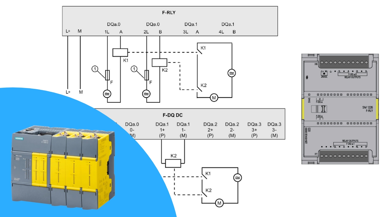
2. Relay Outputs – SM 1226 F-DQ 2 × Relay

The SM 1226 F-DQ 2 × Relay module offers two relay outputs that can switch both DC and AC loads.
Features: slower switching than transistor outputs, full galvanic isolation from the controller, ability to control higher voltages and currents, redundancy through control by two independent microcontrollers (uC1 and uC2).
Typical applications: AC motor contactors, systems requiring galvanic isolation, applications with large inductive loads.
Diagnostics and Safety Mechanisms
Fail-safe output modules are equipped with extensive diagnostic mechanisms:
- Cross-diagnostics – two signal paths (P and M) must operate simultaneously. Any discrepancy causes a transition to the safe state.
- Maximum readback time – the maximum output response time to a state change. Exceeding it is treated as an error.
- Continuous switch tests – cyclic verification of correct operation (OFF→ON→OFF).
- Bidirectional feedback – each channel confirms command execution.
This allows the system to meet the highest requirements of IEC 62061 (SIL) and ISO 13849 (PL).
Safe Output Connection Methods
F-DQ outputs can be connected in various configurations depending on the application:
1. Direct Actuator Connection

A simple solution – e.g., directly controlling a solenoid valve or signal lamp. Used when the actuator has its own safety certificates.
2. P and M Contactors Controlled Independently

The F-DQ channel controls two contactors (for P and M). Only their simultaneous activation powers the load. This increases the safety level and reduces short-circuit risk.
3. Contactors Connected in Parallel

Two contactors in a parallel configuration act as redundancy. In case of one failing, the other still controls the load.
4. Separate Channels for Each Contactor

Each contactor is controlled by an independent output channel. This allows load separation and increased reliability.
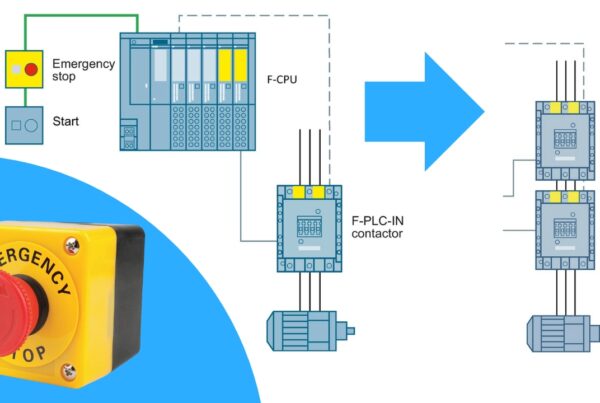
5. Motor Control via Contactors

The F-DQ output is connected to two contactors (K1 and K2). The contactors control the motor. Both must activate simultaneously to provide power. If a discrepancy is detected (e.g., one contactor fails to activate), the F-DQ module transitions to the safe state and cuts power. This solution provides redundancy and eliminates the risk of uncontrolled actuator startup.
Summary
Safe outputs are a key element of every Safety PLC system. Transistor outputs (SM 1226 F-DQ 4 × 24 V DC) are fast and dedicated to DC loads. Relay outputs (SM 1226 F-DQ 2 × Relay) are slower but universal, also supporting AC and providing galvanic isolation. Thanks to diagnostics, redundancy, and various connection options, systems compliant with the highest SIL 3 / PL e requirements can be built. In practice, it is precisely the selection of the appropriate output module and correct wiring that determines whether the safety system will actually work in a critical moment.
👉 Check out our full Safety PLC Course here
Want to master Safety PLC programming? Learn everything from safety principles to real-world configurations in our comprehensive online course.