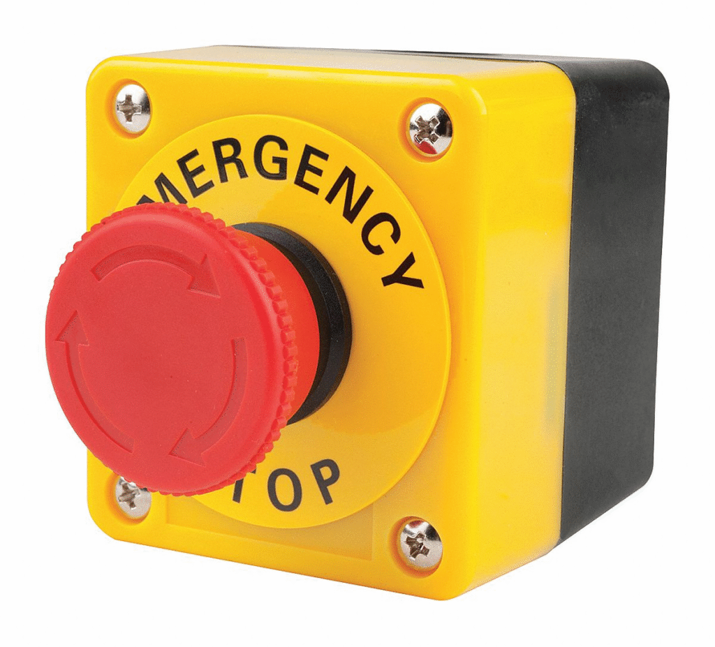
The emergency stop button, commonly known as E-Stop or simply the “mushroom button,” is one of the key safety elements in machines and production lines. Its role is simple: immediately stop the technological process in a situation threatening operator health or machine damage.
In this article, we will look at the basic requirements and categories of emergency stop, E-Stop wiring methods, differences between stop categories 0 and 1, and implementation examples in safety systems.
Theory and Normative Requirements
Standards PN-EN ISO 13850 and PN-EN ISO 13849-1 specify that every E-Stop must meet several basic conditions:
- Red mushroom-head button with yellow background
- Easily accessible to the operator
- Latching action – after pressing, the button must remain in the emergency position until manually released
- Immediate process stop in category 0 or 1
- Reset possible only under safe conditions (additional reset button in case of multiple E-Stops)
Emergency Stop Categories
Category 0 – Immediate power disconnection. Example: after pressing E-Stop, the contactors disconnect the power circuit, and the motor stops by coasting.
Category 1 – Controlled stop with ramp. Example: after pressing E-Stop, the drive receives a Quick Stop signal (e.g., SS1 in a frequency inverter/servo amplifier), and only after a set time is the power cut by contactors or the STO (Safe Torque Off) function.
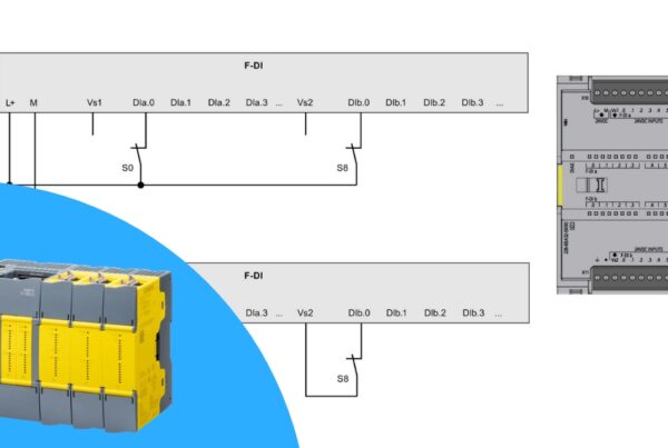
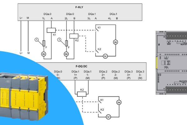
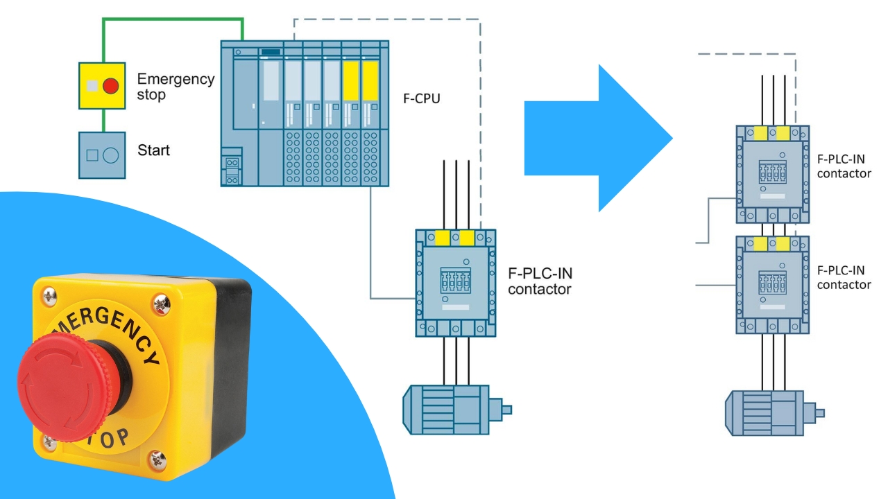
E-Stop Wiring Diagram
A typical E-Stop circuit consists of:
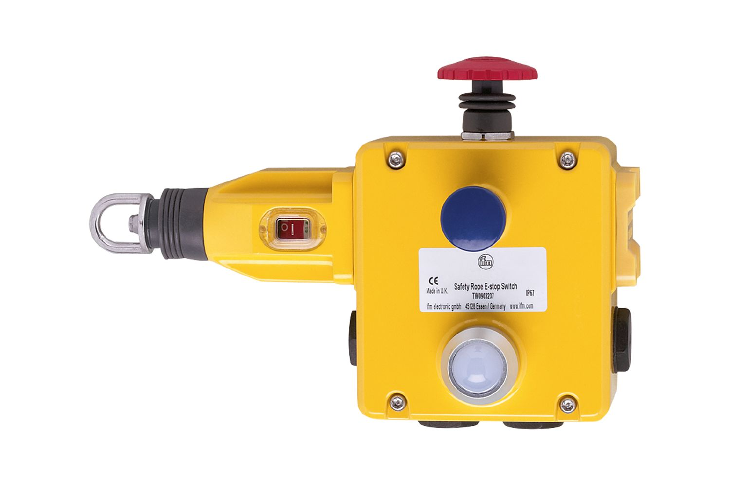
- A button/pull cord with 1 or 2 contacts (usually with forced separation)
- One or two contactors in the power circuit
- An optional reset button
- A safety relay or safety controller
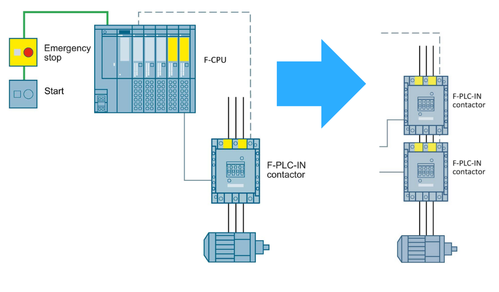
Source: www.siemens.com
By using two contacts and two contactors, we achieve a higher safety level (SIL3/PL e).
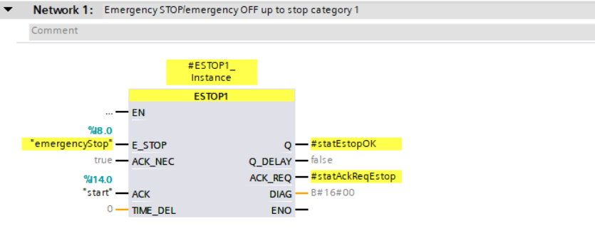
Implementation in the Safety PLC
Siemens provides ready-made function blocks in the Safety Integrated library, such as ESTOP1, which enable implementing the emergency stop function in categories 0 and 1. This block allows for:
- Handling single or multiple E-Stop buttons
- AND logic implementation
- Delayed shutdown function (for category 1)
- Reset and ACK signal handling
Summary
The E-Stop button is a basic but extremely important element of safety systems. Combined with proper logic in the safety controller and appropriate selection of actuating elements (contactors, STO function in drives), it provides effective protection for operators and machines.
👉 Check out our full Safety PLC Course here
Want to master Safety PLC programming? Learn everything from safety principles to real-world configurations in our comprehensive online course.