What Is a Safety Interlock?
A safety interlock is a limit switch with a mechanical key (actuator) that, in addition to signaling the door position, can physically lock the door. The mechanical key is permanently attached to sliding or hinged doors, making it impossible to bypass the system.
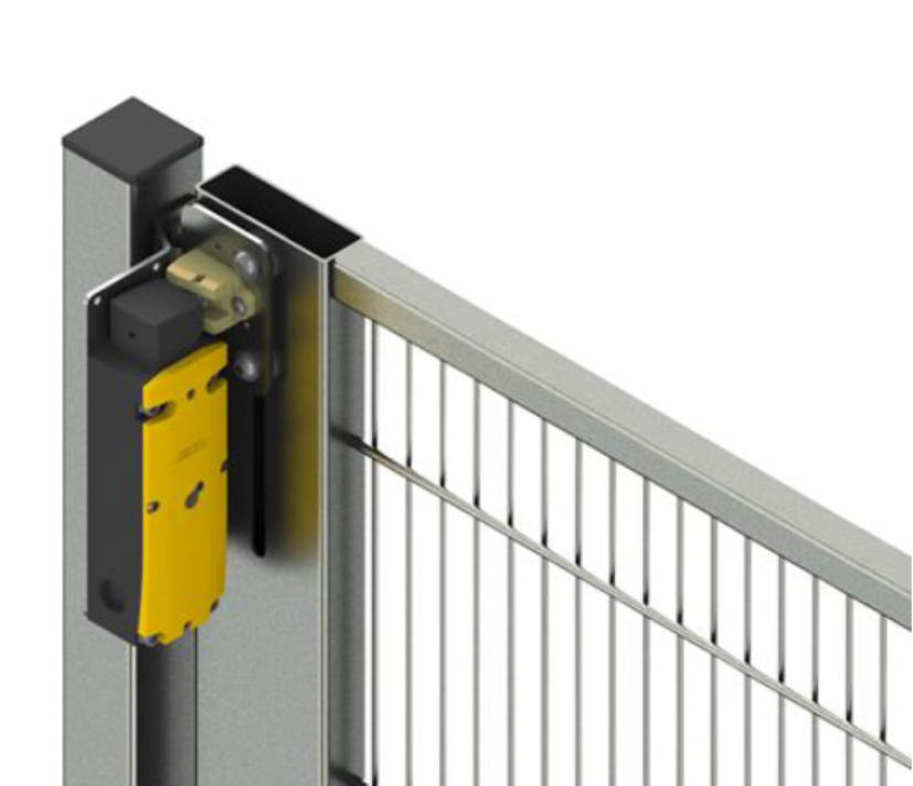
As long as the electromagnet coil in the interlock is not energized, the door remains locked. Opening is only possible after the coil is powered and the mechanism is released. This prevents the operator from opening the door while the machine is in a hazardous state (e.g., a rotating shaft or a machine tool in motion).
In practice, there are two basic types of safety interlocks:
Spring-loaded locking with coil release – In this design, the door is locked by default via a spring mechanism. To open it, the coil must be energized to release the latch. This is a particularly safe solution because in the event of a power loss, the door remains closed, preventing access to the hazard zone.
Normally open with coil latch – Here the situation is reversed. The door is freely accessible, and only energizing the coil locks it. This type is used where, in case of power failure, the door must remain accessible (e.g., for quick operator evacuation from the zone).
The choice of interlock type depends on the application – in machines with a high hazard level, the spring-loaded variant is most commonly used, while in applications requiring safe opening during failure, the coil-latch type is preferred.
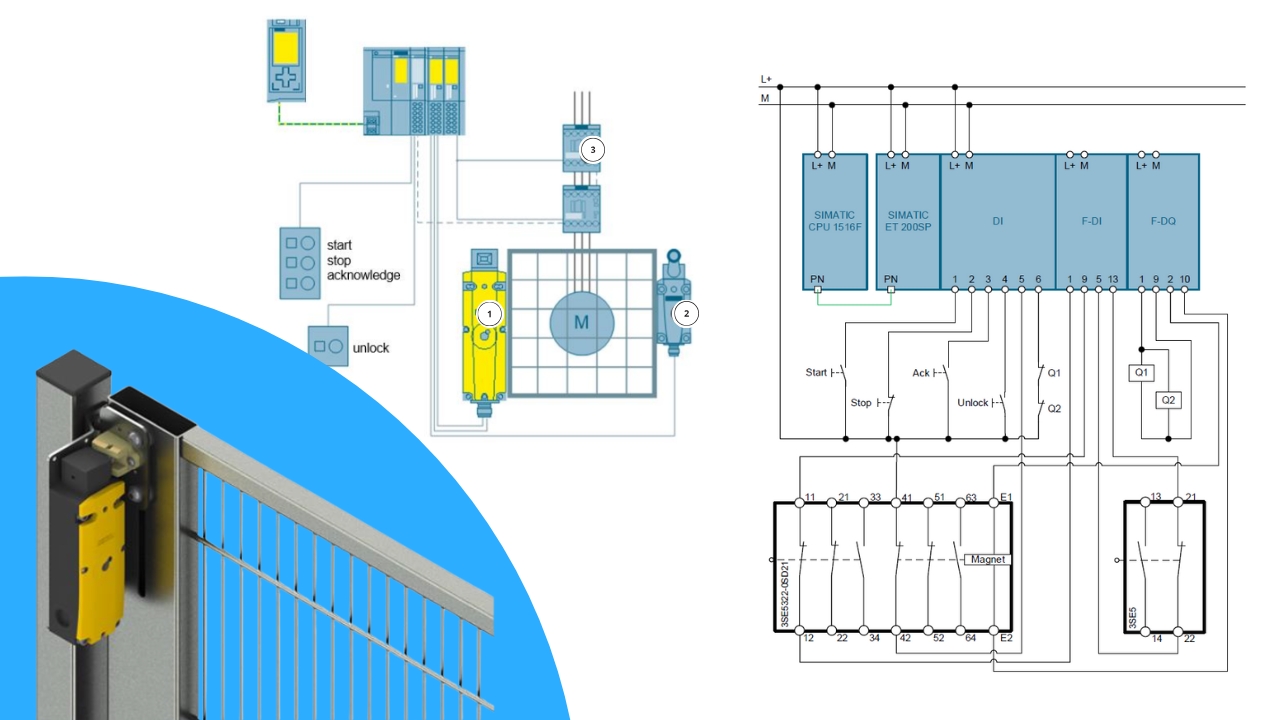
System Structure with Safety Interlock
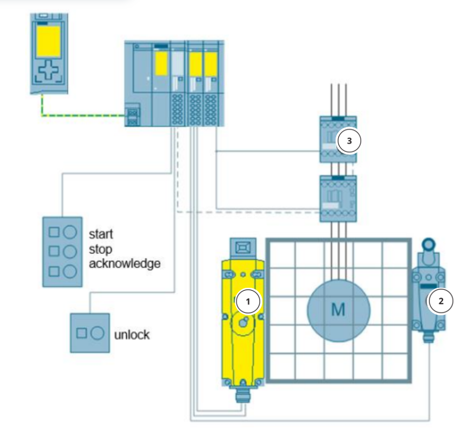
Source: www.siemens.com
- Operator panel: Start, Stop, Reset (Acknowledge) buttons and an additional Unlock button – entry request.
- Safety controller: CPU S7-1500F with ET200SP island, standard and Fail-Safe I/O modules.
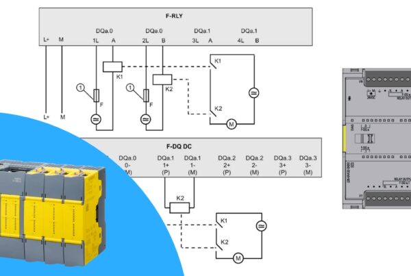
- Contactors Q1, Q2: controlling machine drives, connected to the Safety output module.
- Limit switch (standard): signals door closure.
- Safety interlock: monitors both the door closure state and the electromagnet power state (unlocking).
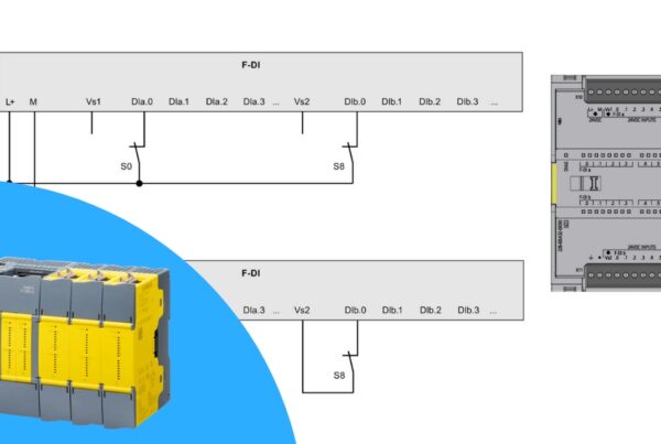
Two Circuits in the Safety Interlock
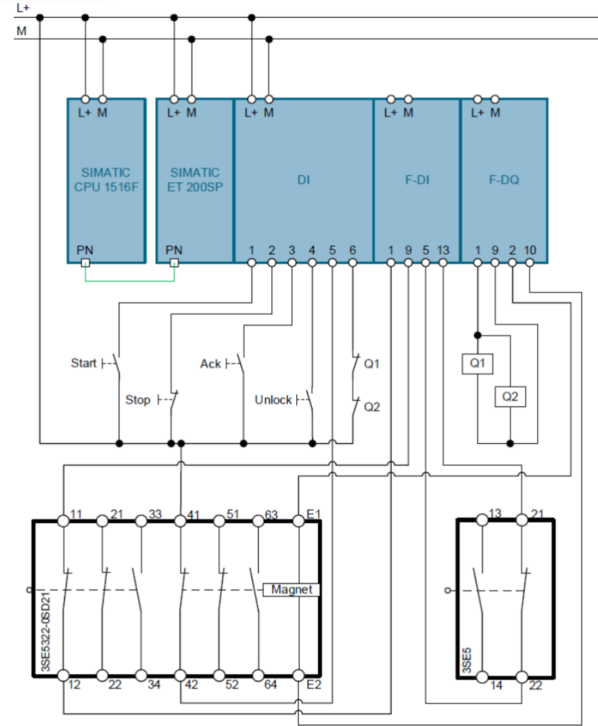
The interlock schematic consists of two contact sections:
Door closure section: NC/NO contacts respond to the presence of the actuator in the interlock. They inform the controller whether the door is closed (but not necessarily locked).
Electromagnet section: NC/NO contacts monitor the state of the coil powering the electromagnet pin. They allow detection of whether the interlock has actually been released.
This enables the system to both control door position and verify the correct operation of the locking function.
Operating Logic
- The operator presses Unlock → the controller sends a signal to the electromagnet coil.
- The interlock releases the pin → the door can be opened.
- The second contact section informs the controller that the interlock has been actually released.
In the PLC logic, we use a feedback mechanism similar to contactor monitoring – we check the consistency of the control signal and the feedback signal.
Documentation and Projects
Siemens provides a ready-made example of this application called: Protective Door with Spring Loaded Interlocking with an S7-1500 Controller.
In the materials you will find: a complete TIA Portal project, PDF documentation, and a TIA Selection Tool file for calculating the Performance Level for the interlock system.
Summary
A safety interlock is a solution used where door monitoring alone is not sufficient – for example in presses, CNC machines, and robotics. It protects the operator from entering the hazard zone until the machine is in a safe state. It provides two independent pieces of information: door closure status and locking status. It works with Safety modules in Siemens controllers, enabling compliance with SIL and PL requirements. This is the next step in building complete safety applications.
Want to master Safety PLC programming? Learn everything from safety principles to real-world configurations in our comprehensive online course.