Digital inputs at first glance are a simple topic. PLCs use them to read the state of a signal – zero (FALSE) or one (TRUE). As a PLC programmer or automation system designer, you must have detailed knowledge about this.
There are a few aspects worth paying attention to:
- Voltage levels of the digital input module (12 V, 24 V, 230 V, etc.)
- Configuration of the input card as sink or source
- Response time and contact bounce
- High-speed digital inputs – HSC
Inputs in the control system
Controllers, such as the Siemens S7-1200 PLC, perform automation tasks through an operation cycle consisting of three key stages:
Reading inputs – The PLC reads the states of digital and analog inputs from sensors, switches, and other devices. In the Siemens S7-1200, both standard 24V digital signals and analog signals (e.g., 4-20 mA, 0-10 V, RTD) can be handled.
Processing the program – After reading the input data, the controller processes the stored program. The program, usually written in Ladder Logic (LAD), Function Block Diagrams (FBD), or Structured Text (ST), analyzes the input states and makes decisions that control the appropriate outputs.
Setting outputs – Based on the program logic, the PLC sends the appropriate signals to the outputs. The Siemens S7-1200 supports both digital and analog outputs, allowing control of various devices, from pneumatic actuators to inverters and servo drives.
In this article, we will focus on digital input signals because they form the foundation for the proper operation of the control system.

Various types of sensor devices and other elements that provide information about the state of the process or machine can be connected to the PLC inputs.
Here is a list of such devices:
| Sensor Type | Description | Sample Product | |
| Proximity Sensors | Used to detect the presence of objects without physical contact | Proximity Sensor Sick Quasi-Flush IMB18-08BNOVC0S | 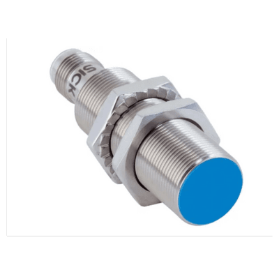 |
| Photoelectric Sensors | Used to detect objects based on changes in reflected or interrupted light | Light Beam Sensor Sick M40E-025023RB0 | 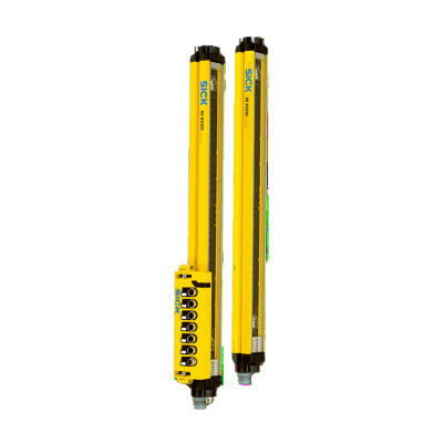 |
| Temperature Sensors | Such as thermocouples or RTD sensors, which measure temperature | Thermometer – Pt100 Resistance Sensor Endress+Hauser | 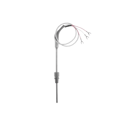 |
| Pressure Sensors | Monitor pressure in pneumatic or hydraulic systems | WIKA A-1200 IO-Link Pressure Sensor | 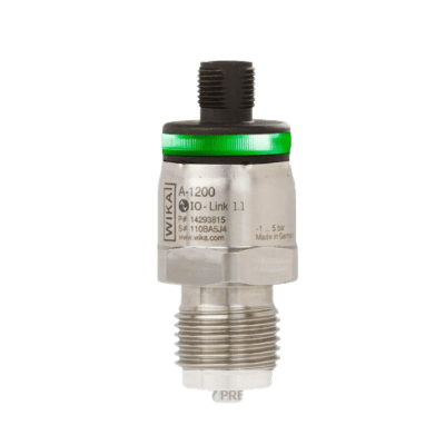 |
| Encoders | Devices used to measure rotational angle or linear position | Turck RE-10S6C Incremental Encoder | 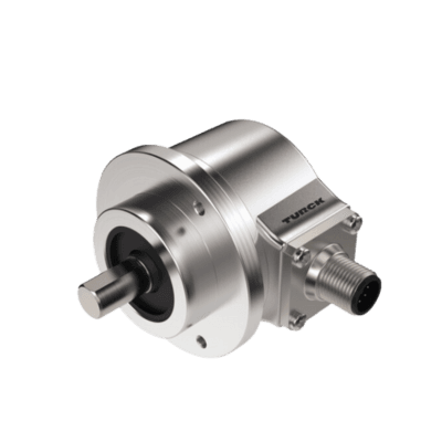 |
| Limit Switches | Mechanical switching devices that activate when a machine element reaches a specified position | Eaton LS-S11/RLA Limit Switch | 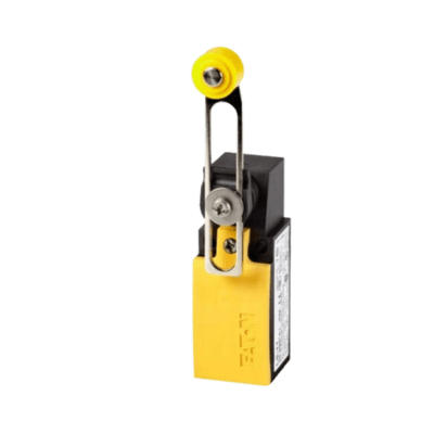 |
| Level Sensors | Used to detect the level of liquids or bulk materials | F&F PZP Liquid Level Float Probe | 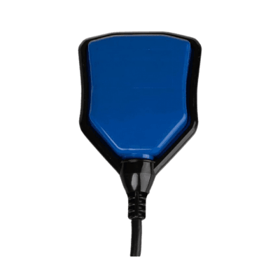 |
| Micro Switches | Small switches activated by a slight physical force | CANAL MPH1512L17P Hermetic Micro Switch | 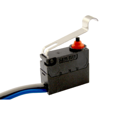 |
| Buttons and Manual Switches | Allow operators to manually input commands | NO Control Button SP22-KLZ-11-230-BA9S | 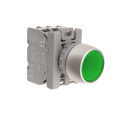 |
How does the Siemens S7-1200 PLC “see” digital signals?
Digital inputs on a PLC, such as those in the Siemens S7-1200 model, operate by detecting two voltage states corresponding to the logical levels “1” (high state) and “0” (low state). The controller interprets these signals based on the voltage applied to its input.
The controller processes these signals within its operating cycle, reading the input states in each scan cycle. The read values are stored in the controller’s memory (in the so-called input memory map) and used for further processing by the control program.
For example, if a 24V voltage signal appears on a digital input, the controller will store a value of “1” for that input. If the signal drops to 0V, the controller will store a value of “0”. In practice, this means that the controller is reading in real-time which devices are on (e.g., sensors, buttons) and which are off, controlling further actions accordingly, based on the stored program.
Low state (Low) – When the voltage at the input drops below a certain value (often below 5V or 0V), the controller reads this as a logical “0”. This means that the input signal is inactive or off. In practice, if the sensor or switch on the input line does not provide voltage or the signal is zero, the controller interprets this as no signal.
High state (High) – When a voltage corresponding to the defined logical “1” level appears on the digital input (most often this is the VCC supply voltage, e.g., 24V DC in industrial systems), the controller recognizes that the input is active. For Siemens S7-1200, a voltage above a certain threshold (e.g., 15V) is usually interpreted as a logical “1”.

Digital inputs in the S7-1200 PLC – galvanic isolation
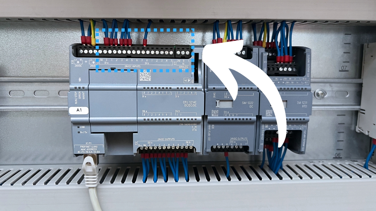
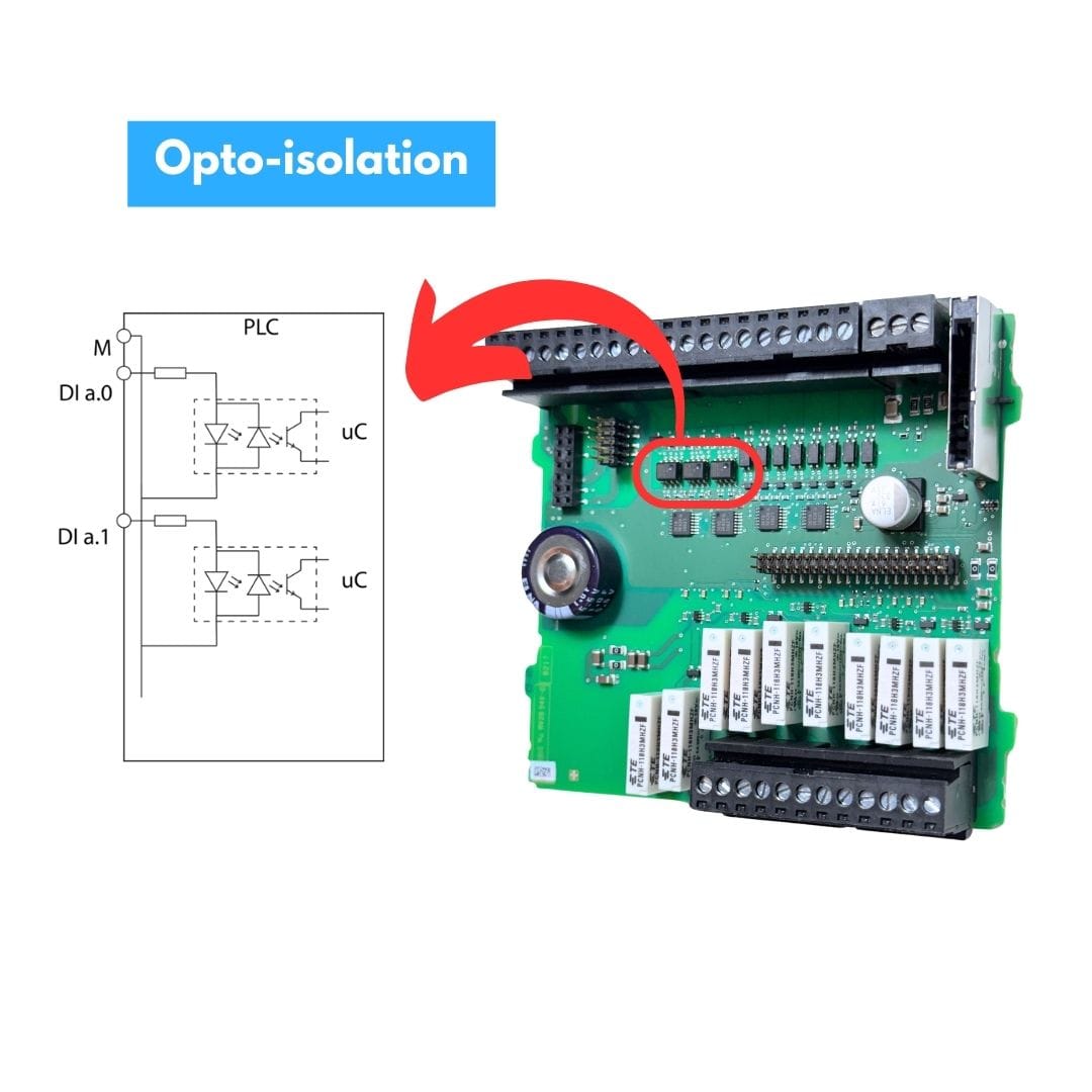
The attached photo shows a fragment of the Siemens S7-1200 controller board, specifically the section responsible for digital inputs. The upper part of the board has a row of screw terminals used to connect signal wires responsible for introducing digital signals into the controller. These terminals enable connecting sensors, switches, and other peripheral devices that generate digital signals.
Galvanic isolation between the digital input section and the central processing unit (CPU) in the Siemens S7-1200 controller is a key element ensuring safe and reliable operation of the entire control system. This is achieved through the use of optoisolators, which act as an electrical barrier between the input signal circuits and the CPU logic circuits.
Optoisolators, also known as optocouplers, consist of two main components:
- LED (on the input side),
- Phototransistor (on the output side).
When a signal appears on the digital input, the current flowing through the LED causes it to light up. This light is detected by the phototransistor on the output side, which responds to the signal and transmits it to the CPU. The key aspect is that there is no direct electrical connection between the LED and the phototransistor – signal transmission occurs exclusively optically. This ensures that no electric current flows between the input section and the CPU, protecting the central unit from overvoltages, interference, or damage from external signal sources.
Digital inputs in PLC – response time and contact bounce
In Siemens PLCs, the response time to changes in the digital input state is crucial for the proper functioning of the system. One common issue encountered is contact bounce – brief, random signal changes that can occur with mechanical switches (e.g., relays) or buttons.

These bounces cause the signal to change multiple times in a short period before stabilizing, which can lead to incorrect readings by the controller.

In the Siemens S7-1200, we have the option of using input filters that eliminate these undesirable effects. By adjusting the filtering time, for example, setting it to a few milliseconds, the controller ignores short disturbances and only reacts to signals that persist for a specified time. The graph shows how contact bounce affects the input signal, and proper filter settings allow for stable readings without false state changes. Optimizing this parameter significantly improves the reliability of the control system.

PLC input types – Sink/Source
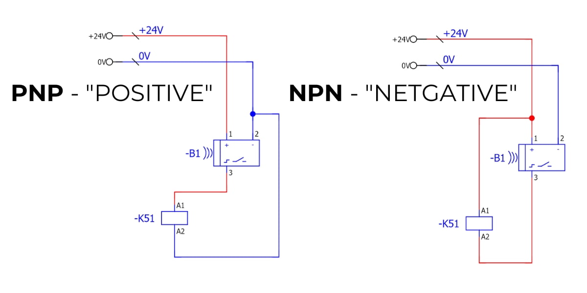
We distinguish between two types of inputs, which can be either “sink” or “source” inputs, depending on the configuration chosen and the type of sensors used in the project.
In Europe, PNP-type sensors and sink input cards are most commonly used. In Asia, however, the opposite approach prevails, where NPN-type sensors and source input cards are predominant.
Sink Inputs
In this case, the sensor supplies a 24V VCC potential to the controller (e.g., to DI a.0), and the digital input circuit is closed by connecting terminal 1M to ground (GND).
Source Inputs
Here, the circuit is closed by connecting terminal 1M to the power supply (VCC). The channel is activated when the sensor connects the input, e.g., on DI a.0, to a 0V (GND) potential.
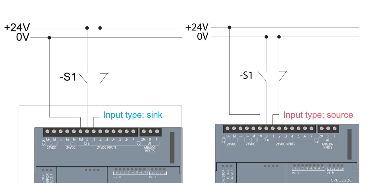
Analyze the connection diagram of the Siemens S7-1200 CPU 1211C DC/DC/DC controller below. Note that you can configure the digital inputs in both sink and source modes, depending on how they are wired.
If you want to use inputs in sink configuration, you should connect the negative wire (“-” 0V) to terminal “M”. In the source configuration, you should connect the positive wire (“+” 24V) to terminal “M”. This flexibility allows the configuration to be adapted to the installation’s needs and the type of peripheral devices, which may require different signal detection methods.

Below are two ways to connect sensors to the controller. The first is a source sensor with a sink controller, and the second is the reverse – a sink sensor with a source controller. WARNING! A source sensor connected to a source controller will not work!
High-Speed inputs (HSC)
In the Siemens S7-1200 controller, high-speed digital inputs (HSC – High-Speed Counters) are designed to handle high-frequency signals that standard digital inputs cannot accurately read due to timing limitations.
High-speed inputs (HSC) are particularly useful in applications such as speed measurement, pulse counting, reading encoder positions, or controlling precise processes requiring fast reactions.
Applications of high-speed inputs (HSC) in PLC S7-1200:
- HTL Encoders: Used to measure the speed or position of motors and other devices.
- Proximity Sensors: For quickly detecting objects in processing or packaging applications.
In the Siemens S7-1200 controller, two types of HSC (High-Speed Counter) channels are available, differing in the maximum signal reading frequency:
- High-Frequency HSC Channel – Handles signals up to 100 kHz. This is the main channel, designed for applications requiring high precision, such as counting pulses from encoders or high-speed sensors.
- Lower Frequency HSC Channel – Handles signals up to 30 kHz. This channel is used in less demanding applications where lower-frequency signals are sufficient.

Digital input modules
The S7-1200 controller offers built-in digital inputs and the possibility to expand the system with additional modules. The following digital input modules are available:
- SM 1221 (8 inputs): Module with 8 digital inputs, operating voltage 24VDC,
- SM 1222 (16 inputs): Module with 16 digital inputs, operating voltage 24VDC,
These modules can be cascaded, increasing the number of available digital inputs in the system.

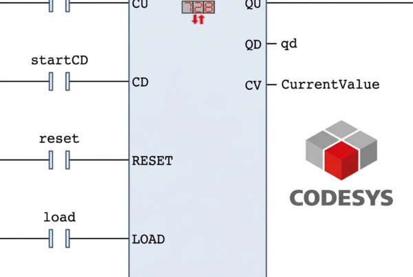
Learn the Siemens S7-1200 PLC programming language
Conclusion
When designing a system using the Siemens S7-1200 PLC, it is crucial to pay attention to several key aspects regarding digital inputs. Programming the Siemens S7-1200 PLC requires the proper selection of digital input voltage levels (12 V, 24 V, 230 V), as well as configuring inputs as sink or source, which affects how they are connected to sensors. Another important factor is optimizing the input response time and eliminating contact bounce to ensure accurate readings. For applications requiring fast signal processing, it is worth using high-speed digital inputs (HSC). These factors directly impact the reliability of a control system based on the Siemens S7-1200 PLC.
Siemens S7-1200 PLC Tutorial Outline: