Why is entering the world of automation and programming a challenge?
Entering the world of automation is challenging for several reasons:
- Knowledge related to software development is protected by companies that produce machinery and automation systems.
- Example programs are not readily available on the internet.
- Automation software (e.g., Siemens TIA Portal) is expensive.
- Training in basic programming is costly (1,500-5,000 EUR).
Equipment is expensive – a basic PLC + HMI starter kit costs around 1000 EUR.
My name is Jacob Biedulski, and I remember my own beginnings (more than 10 years ago) when I was an intern and wanted to start programming PLCs. PLC programming training was far beyond my reach – it cost more than two months’ salary! An experienced automation engineer shared his notes from the training that his company had sent him to – that was my start. I remember how the copier was red-hot as I finished copying over 1,000 pages of training materials. While working at the company, I had access to machine programs, where I could study professional-level programs.
Those were my early, incredibly tedious beginnings. Later, I got a job at an integration company and worked on various projects – testing machines, technological systems, and robotic stations. I turned the knowledge I gained into the ControlByte training platform and my own company with a team of engineers and programmers, delivering custom machine orders.
Why Programmable Logic Controllers (PLCs)?
The production of most consumer products, ranging from food to electronics, takes place in automated facilities. These goods are then distributed and delivered through automated systems, reducing the need for human involvement. Automation in manufacturing is not a new idea, as machines consistently outperform humans in terms of efficiency, precision, and consistency in large-scale production. Consequently, there is an ongoing effort to automate every stage of the manufacturing process.
Various automation systems are utilized across different areas of production, all aimed at achieving similar goals: reliability, repeatability, and easy maintenance. This demand led to the creation of Programmable Logic Controllers (PLCs) in the previous century.
PLCs were introduced to replace complex relay-based systems, offering a simpler way to change operations and boost system reliability.
Designed to be a cost-effective replacement for relays, PLCs emerged a few years after transistors became mainstream. Essentially, a PLC is a highly reliable computer capable of running programs continuously, 24/7, in a demanding environment.
While PLCs were initially straightforward to set up, their complexity grew as business requirements evolved, and production floors became more intricate. Consequently, businesses needed individuals skilled in PLC programming to design, optimize, and adjust programs based on operational demands.
A Programmable Logic Controller (PLC) is essentially the hardware responsible for managing and controlling processes. Physically, a PLC resembles a box filled with electrical circuits, similar to a desktop computer. It is typically enclosed in a protective case to shield it from the harsh conditions it might face in industrial environments. Often, when referring to PLCs, we are discussing the entire control system on the factory floor, as PLCs are connected to a range of devices like sensors, motors, switches, and valves.
Since their invention, PLCs have significantly advanced. While they remain robust machines designed for process control, they are now integrating features commonly found in the IT sector. For example, PLCs now offer Ethernet connectivity for data collection, sensor monitoring using technologies like IO-Link, and server-based connections using MQTT protocols, among others. Simply put, PLCs have evolved far beyond what they were just a few decades ago.

As manufacturing facilities around the globe rely heavily on PLCs, and the technology continues to evolve, there is an increasing need for experts capable of developing, supporting, and managing these systems.
Various Routes to Becoming a PLC Programmer
There are multiple ways to become a skilled PLC programmer. You could pursue a traditional university degree, learn through online tutorials, or enroll in a course that provides a PLC programming certification upon completion. But which option is the most suitable, and which certifications hold the most value?
Engineering and Engineering Technology Degrees
A bachelor’s degree in electrical engineering, a related discipline, or engineering technology is a common route into the field of industrial automation. Many universities offer programs that include topics such as PLC programming, HMI development, robotics, and control systems. At the end of the program, graduates receive a degree that often holds more prestige than a standard PLC programming certification, particularly from a well-recognized university.
While a university degree may be the right choice for some, it typically requires a commitment of three to four years, along with significant financial investment, and may not always guarantee the desired job outcome. Another downside is that not all courses may focus on automation, and students might find themselves studying subjects like calculus, linear algebra, chemistry, and more that aren’t directly related to PLC programming.
Official OEM PLC Programming Certifications and Courses
Major OEMs like Allen Bradley, Siemens, Wago, Beckhoff offer PLC programming certifications and training sessions that focus on developing specific skills. These courses are usually held in person, taught by professionals, and can last from a single day to several weeks.
Although obtaining a PLC programming certification from these classes is possible, it often doesn’t hold as much value as students expect. While these sessions will teach participants how to program PLCs, they often lack hands-on projects, assignments, or tests that challenge students to think critically about the material presented.
Many engineers we’ve spoken to have expressed disappointment with these courses, both in terms of the learning experience and how much weight their PLC programming certification carried when job hunting. The common frustrations include:
- No completed projects
- Information overload
- Certifications not valued by employers
- High cost
For instance, a typical Siemens PLC programming course can cost between EUR 1,500 to 5,000. While companies may cover this as an investment in their employees, it is often out of reach for individuals looking to learn independently.
Online PLC Programming Certifications
While online learning has been around for a while, the field of PLC programming, industrial automation, and control systems is still evolving in this regard. There is a broad spectrum of quality when it comes to PLC programming certifications offered by various organizations.
Below is a checklist of factors you should consider when choosing an institution to provide your PLC programming certification:
- Instructor’s Experience – Does the instructor have real-world industry experience, or are they solely an educator? While it’s possible to learn control systems academically, hands-on industry experience is invaluable. Instructors who have practical knowledge will be able to highlight what’s most important, share industry-specific insights, and help you prepare for real-world challenges and interviews.
- Issuing Organization – What will potential employers find if they research the organization that issued your certification? Is the provider a recognized expert in their field, or are they just an aggregator of certification programs?
- Project-Based Learning – Will you be involved in hands-on projects during the course? Will the projects challenge you as you absorb new concepts? These practical applications are crucial to ensure you can apply your knowledge in real-world problem-solving, system design, or from-scratch development.
- Reputation – What do others say about the certification program? Has it been valuable for previous participants?
Key Benefits of an Online PLC Programming Certification
Lower Cost – Online certifications tend to be much more affordable compared to in-person courses. We usually advise students to use part of the money saved to invest in a small training kit that can be useful for years to come, which they can showcase during job interviews and use to continue honing their skills after completing the course.
Learn at Your Own Pace – For years, the value of flexible learning has been underestimated. With online materials, you can pause and resume lessons at any time with the click of a button. Unlike traditional classroom settings, online certification allows you to spend as much or as little time on specific subjects as needed. This flexibility helps you master concepts at your own pace and revisit lectures before job interviews, ensuring a solid grasp of the material.

Projects, Assignments, and Quizzes – An online PLC programming certification provides opportunities for hands-on learning through projects and assignments, which students complete independently. These tasks are essential for reinforcing key concepts taught during lectures and ensuring a deeper understanding of the material.
While we encourage you to explore various options for PLC programming certifications, we firmly believe that a comprehensive online program offers the knowledge you need and a certification that can help you secure a job—all without the high costs associated with in-person courses.
Introduction to TIA Portal
TIA Portal (Totally Integrated Automation Portal) is Siemens’ all-in-one software suite designed for industrial automation, specifically for programming Siemens PLCs (Programmable Logic Controllers). It integrates programming, configuring, and diagnosing in one environment, making it easier for automation engineers to design and maintain control systems. Whether you are a beginner or an advanced user, TIA Portal offers a comprehensive set of tools to create, simulate, and troubleshoot industrial automation projects.
In this chapter, we will introduce you to the basics of TIA Portal and walk you through the first steps of PLC programming. By the end, you’ll be familiar with the essential functions and ready to create your first project.
Which version of TIA Portal should you install?
Since 2015, Siemens has released the following versions of TIA Portal:
- TIA Portal V13 SP1 (2015) – Service Pack for V13.
- TIA Portal V14 (2016) – Introduced enhanced usability and cloud-based options.
- TIA Portal V14 SP1 (2017) – Further improvements and bug fixes.
- TIA Portal V15 (2017) – Major update with increased functionality for Siemens PLCs and SCADA integration.
- TIA Portal V15.1 (2018) – Mid-cycle release, improving performance and introducing minor features.
- TIA Portal V16 (2019) – Significant updates with enhanced libraries, Teamcenter integration, and expanded simulation tools.
- TIA Portal V17 (2021) – New features such as OPC UA Client, extended diagnostic functions, and advanced simulation capabilities.
- TIA Portal V18 (2022) – Focused on improving cloud connectivity, collaboration tools, and edge computing integration.
- TIA Portal V19 (2023) – Introduced AI and machine learning capabilities, advanced cybersecurity, and extended support for edge devices.
So, since 2015, there have been 9 versions of TIA Portal (including service packs and major updates).
Managing TIA Portal versions in automation projects
One of the critical aspects of managing automation projects with Siemens TIA Portal is ensuring that each project is maintained using the same TIA Portal version throughout its lifecycle. Automation projects are highly sensitive to software version changes, and inconsistent versioning can lead to significant challenges in functionality, compatibility, and troubleshooting.
When you begin developing or maintaining a project, it’s essential to use the same version of TIA Portal that was initially used to create or configure the system. Here’s why:
- Compatibility: Projects developed in one version of TIA Portal may not be fully compatible with later versions. Upgrading or downgrading a project can cause issues with hardware configuration, block execution, or system diagnostics.
- Project Integrity: Even small changes in the software version can affect the logic execution, communication protocols, or data handling, which can disrupt system performance in production environments.
In the industrial world, it’s common for automation engineers to work on multiple systems or machines, each of which may have been developed using different versions of TIA Portal. To handle this, there are two main strategies:
Install Multiple TIA Portal Versions
One practical solution is to have multiple versions of TIA Portal installed on your workstation or engineering machine. Siemens allows you to install different versions side by side, which makes it easier to maintain and troubleshoot different projects without upgrading them. This approach ensures that each project remains in its original version, maintaining full compatibility and stability.
Benefits of Multiple Versions:
- No Risk of Compatibility Issues: You can open and edit projects in the exact version in which they were developed, reducing the risk of errors or issues caused by version mismatches.
- Familiarity with Existing Systems: Older machines or systems may rely on specific versions of TIA Portal, and keeping those versions allows for easy access and consistent performance.
How to Manage Multiple Versions:
- Install Side-by-Side: Siemens allows multiple versions of TIA Portal to coexist on a single system. For example, you can have TIA Portal V15, V16, and V19 installed without conflicts.
- Version Labeling: Be diligent in labeling your project files and folders to indicate the TIA Portal version used, so you always know which version to open for specific projects.
Upgrade Projects to the Latest Version
Another approach is to upgrade entire projects to the latest version of TIA Portal, such as V19. While this might simplify your software environment by reducing the number of TIA Portal versions installed, it’s not without risks and challenges.
Free license for TIA Portal
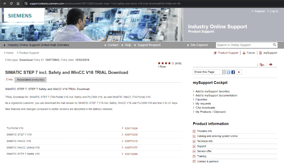
Siemens offers a free 21-day trial license for TIA Portal, allowing users to explore and test the software without committing to a full purchase.
This trial version provides access to nearly all the features of the full version, enabling engineers to create, simulate, and test PLC programs, HMI interfaces, and automation systems. It’s an excellent opportunity for beginners to familiarize themselves with TIA Portal or for experienced professionals to evaluate the latest version before making a purchase decision. The trial can be easily downloaded from Siemens’ website, and no hardware dongle is required during the trial period.
Which version of TIA Portal should you choose to start learning
As you can see, you have 21 days of trial for every TIA Portal version. Currently, Windows 11 is the latest operating system compatible with TIA Portal. If you want to start learning, I suggest beginning with version V16. When your 21-day trial period ends, simply download and install TIA Portal V17. Once that trial ends, you can move on to TIA V18, and then V19.
This way, you can extend your trial period to over 84 days in total.
Free PLC simulator – PLCSIM from Siemens
PLCSIM is a free PLC simulator offered by Siemens, which allows users to simulate and test their PLC programs without the need for physical hardware.

It is integrated into the TIA Portal software environment, making it easy to simulate automation systems directly from the programming interface. With PLCSIM, engineers can test ladder logic, function blocks, and other programming structures in a virtual environment. This tool is especially useful for troubleshooting and validating logic before deploying it to a real PLC.
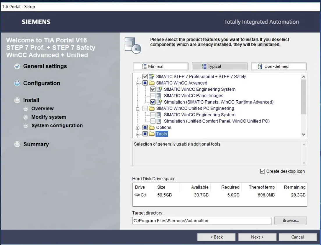
TIA Portal Installation
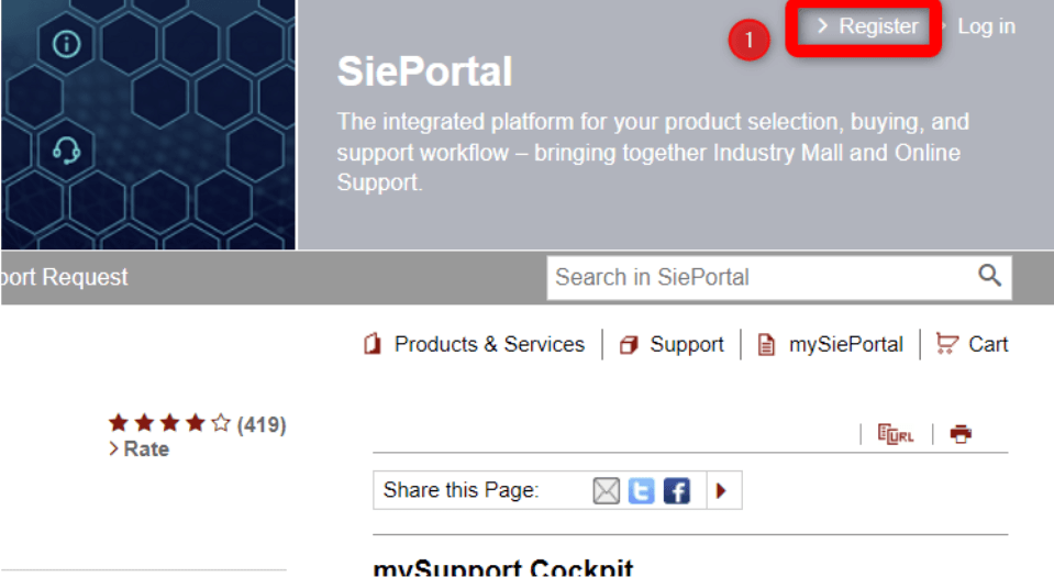
STEP 1
STEP 2
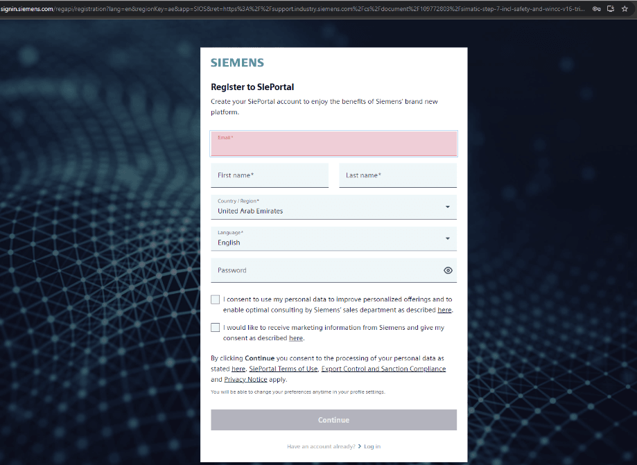
Click Register and create your account
STEP 3
Fill the form and create your account.
STEP 4
And download files marked in red (1) and (2).
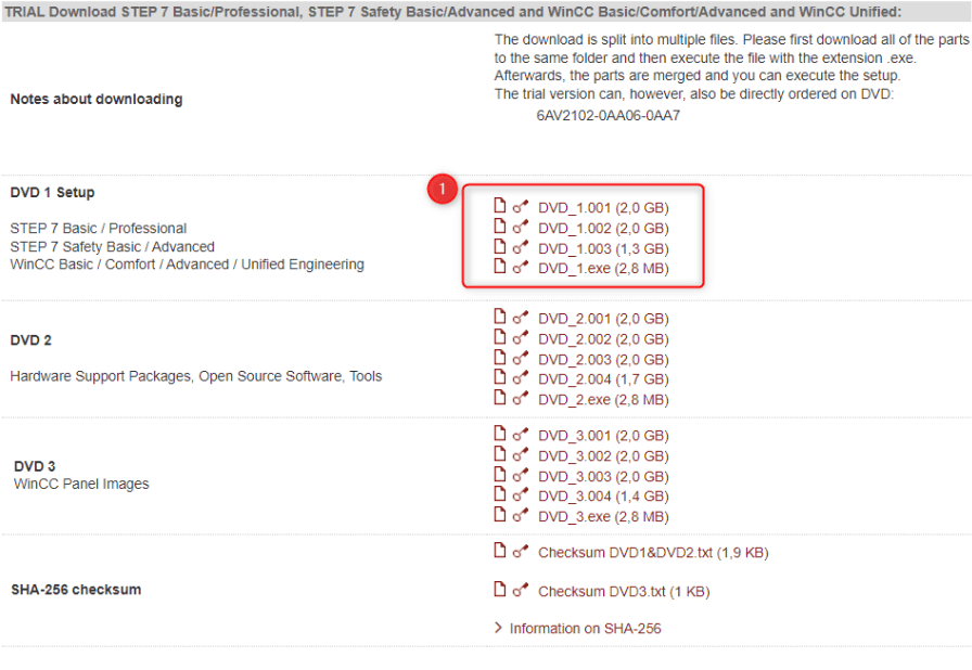

STEP 5
After downloading the files, move them all into a single directory and then double-click on the “TIA_Portal_STEP7_Prof_ Safety_WINCC_Adv_Unified_V16.exe” to start the installation
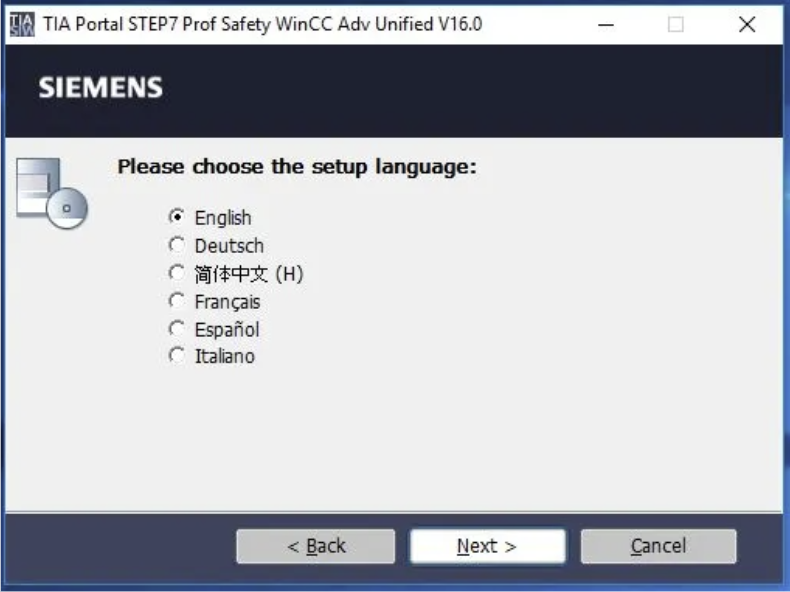

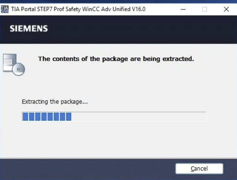
STEP 5
After extracting the files the installation will start automatically. Proceed with the installation as follows.


STEP 6 – Install PLCSIM
After finishing the installation of STEP7, click on “SIMATIC_S7PLCSIM_V16.exe” and proceed with the installation of PLCSIM in the same way.
STEP 7 – Write your first PLC program
Great! You have TIA Portal installed and now you are ready to start coding!
If you want to write your first program on Siemens PLC, check our free entry PLC training here:
PLC PROGRAMMING LANGUAGES
Once you’ve selected your platform, the next step is choosing a programming language. PLCs can be programmed in several languages, including:
- Ladder Logic – LAD
- Function Block Diagrams – FBD
- Structured Text – ST (SCL for Siemens)
- Sequential Flow Charts
- Instruction List – IL (STL for Siemens)
While it may be tempting to choose a programming language based on its simplicity or how familiar it feels, it’s recommended that you start with ladder logic. This is because ladder logic is the most common and widely used programming method, originating from relay logic. It’s known for being easy to implement and debug.
The core of ladder logic consists of three main instructions:
- -| |- Normally Open (NO) contact
- -|\|- Normally Closed (NC) contact
- -( ) Coils
At this stage, it’s important to focus on mastering rung structures and branching.
Begin by building simple logic routines using the above instructions. Pay attention to how they affect the boolean states they’re connected to and try different rung configurations. As you create these different structures, consider how they interact and their impact on the overall logic.
We will explore each of these topics in greater detail in the following chapters.
Before diving into Ladder Logic, it’s crucial to understand the various PLC programming languages and their distinctions.
The top 5 most widely-used PLC programming languages as of 2020 are:
- Structured Text (ST)
- Sequential Function Charts (SFC)
- Ladder Diagram (LD)
- Function Block Diagram (FBD)
- Instruction List (IL)
The International Electrotechnical Commission (IEC) 61131-3 standard defines 5 different PLC programming languages: ladder logic, structured text, function block diagrams, sequential function charts, and instruction lists. Each language has its strengths, limitations, and most suitable use cases. To be an effective PLC programmer, it’s important to be familiar with all of these options for troubleshooting, selecting the right tool for the job, and gaining different perspectives on problem-solving.
Additionally, the availability of certain languages may depend on the PLC platform being used, with some requiring a more advanced license or not offering support at all. For instance, only the full version of TIA Portal and S7-1500 PLC offers access to IL and SFC.
In the next sections, we will take a closer look at each of these languages, reviewing their structure, applications, and common use cases.
What is the most popular programming language for a PLC?
This question is often discussed among PLC programmers worldwide. The general agreement is that ladder logic is the most commonly used language for PLC programming. This is because ladder logic is highly versatile, easy to learn, and well understood, particularly by electricians who are familiar with schematics that mirror this architecture.
However, in the past decade, a younger generation has entered the manufacturing industry. These newer engineers and technicians are typically trained in modern languages like Java, Python, and JavaScript. Since these languages share similarities with Structured Text (ST), there has been an increase in the use of ST in PLC programming.
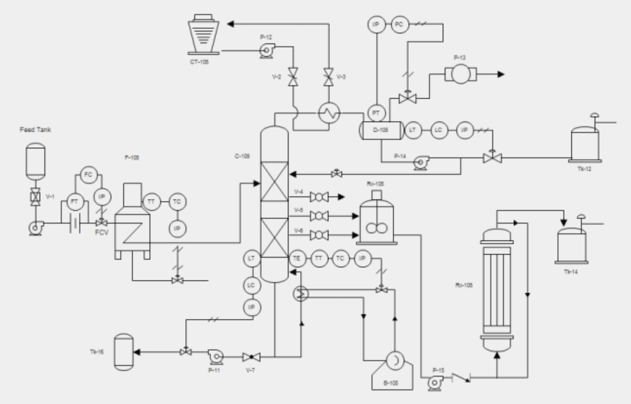
Additionally, the industry in which the PLC is being used also plays a significant role in determining the language of choice. For instance, chemical processes are often designed using Piping & Instrumentation Diagrams (P&ID). These diagrams can be easily translated into PLC programs using Function Block Diagrams (FBD).
Ladder Logic
Before the advent of Programmable Logic Controllers (PLCs), relay-based systems dominated most manufacturing processes. These relays controlled loads based on simple logic, which was implemented through the physical wiring of the devices. Electrical schematics were designed to represent these relay circuits in a format resembling a ladder. When PLCs were introduced, ladder logic programming was developed to replicate the layout of these relay-based circuits. As a result, ladder logic became one of the earliest PLC programming languages and remains widely used today because of its simplicity.
Since its development, ladder logic has undergone significant advancements, but its core operational principles remain largely unchanged. Ladder logic programming evaluates conditions in a sequential manner, much like the original relay systems.
Advantages of Ladder Logic in PLC Programming
- Easy to Implement and Troubleshoot – Ladder logic is a visual programming language that provides clear confirmation of the status for most instructions. This makes it simple for users, even those with limited knowledge of a process, to follow the program flow and understand the logic.
- Modular Design – Ladder logic is highly modular, allowing easy modifications by adding or removing logic. Each rung represents a separate condition, which can be modified as needed without affecting the rest of the program.
- Resilience and Consistency – Ladder logic allows for the implementation of many functions while maintaining a standardized format. While it doesn’t offer full flexibility, its standardization ensures consistency across different implementations, making the code reliable and easier to maintain.
Drawbacks of Ladder Logic
- Steep Learning Curve – While Ladder Logic is a simple language, it may not be intuitive for individuals with experience in languages like C, C++, Java, or Python. However, those with backgrounds in electrical engineering or assembly programming may find it easier to grasp.
- Slower Development – Due to its visual interface, Ladder Logic can take more time to develop. The drag-and-drop nature of the interface often slows down the process compared to other modern programming languages.
- Not Ideal for Complex Applications – Ladder Logic excels in handling sequential boolean logic, but it becomes less efficient when dealing with more advanced control systems like PIDs, flow control, and feedback loops. These more complex tasks are harder to implement and understand using Ladder Logic.
Despite these drawbacks, Ladder Logic remains the most widely used PLC programming language globally. It’s relatively easy to maintain and work with, especially for users who don’t have constant exposure to PLC programming.
Structured Text
Structured Text (ST) is a PLC programming language that is similar to C or Pascal. It allows the user to input lines of code that execute in sequence, perform specific functions, evaluate boolean conditions, and activate the corresponding outputs of the PLC. For individuals with experience in traditional programming languages such as C, C++, Java, or Python, Structured Text offers a smooth transition into the world of PLCs. Additionally, it can be easily modified in text editors, making it quick to implement without the need for physical hardware.
Advantages of Structured Text in PLC Programming
- Familiarity for Programmers – Structured Text is intuitive for those with a background in software development, especially in languages like C or Java. It uses similar structures, programming principles, and functions, making it easier for programmers to transition into PLC programming.
- High Flexibility – Structured Text offers more flexibility compared to other PLC programming languages, allowing for the implementation of more complex functionalities. This makes it a powerful tool for advanced users.
- Cross-Platform Compatibility – Structured Text is standardized across most PLC systems, which means it can be easily migrated between different platforms. Unlike other languages that can vary significantly between systems, Structured Text provides consistency across both hardware and software environments.
Disadvantages of Structured Text
- Challenging to Troubleshoot – Compared to ladder logic, Structured Text can be harder to troubleshoot. It lacks visual cues and often requires more lines of code, making it difficult for those unfamiliar with the language to trace and diagnose issues within the process.
- Prone to Errors – While offering greater flexibility, Structured Text sacrifices some of the standardization found in other PLC programming languages. This requires programmers to adhere to best practices, such as including fallback mechanisms and error handling, to prevent potential failures in the system.
We generally advise learning Structured Text only after you’ve gained a solid understanding of Ladder Logic, unless you have experience in another programming language. Due to the challenges associated with Structured Text, it’s not commonly used in production environments. However, it’s highly effective for tasks such as data manipulation, implementing FOR loops, and handling other structures that would require more complex steps in Ladder Logic.
Function Block Diagrams
Function Block Diagram (FBD) is a programming language created with chemical processes in mind. It enables users to visually represent the process flow, using appropriate transitions between instructions. The visual editor is intuitive and user-friendly, providing a natural approach for implementing specific process flows.
In PLC programming, one of the most common uses of Function Block Diagrams is for establishing PID controllers. The visual nature of FBD makes it simple to implement, visualize, tune, and troubleshoot PID controllers directly in the field.
Advantages of Function Block Diagrams in PLC Programming
- Flexible Visual Editor – The Function Block Diagram editor is highly user-friendly and allows for simple creation of any layout. It provides an easy-to-use interface for building process flows.
- Ideal for Complex Programming Structures – In ladder logic, multiple rungs may be required to handle complex tasks. In contrast, FBD allows for direct implementation of complex instructions, such as those for PID loops, motion control, and Add-On Instructions (AOIs), on a single page.
- User-Friendly – The visual editor in FBD is intuitive for most users. It employs a drag-and-drop system, making it easy to recreate process layouts without much guesswork.
Disadvantages of Function Block Diagrams
- Difficult to Standardize – Due to the flexibility of the layout, it can be hard to standardize programs created in FBD. Each programmer may develop a different approach, which can make it difficult for others to follow the flow of information.
- Challenging at Larger Scales – FBD works well for small-scale implementations. However, as the program complexity increases, it’s easy to get lost in the multiple sheets of instructions.
Function Block Diagrams are particularly useful for analog scaling, PID loops, and motion control sequences. As you become familiar with these areas, it’s beneficial to start learning FBD. However, we recommend mastering ladder logic before moving on to FBD.
Sequential Function Charts
As the name suggests, Sequential Function Charts (SFC) are ideal for processes that need to follow a specific order. Another example would be an automated car wash process that ensures vehicles are cleaned efficiently and in the correct sequence.
Imagine a fully automated car wash system with various stages such as pre-wash, soaping, brushing, rinsing, and drying. When a vehicle enters the system, the process follows a series of predefined steps. Here’s a simplified version of those steps:
Step 1 – Vehicle detection and preparation: The system detects a vehicle at the entrance. It checks if the car is properly aligned on the conveyor, the washing area is clear, and all systems are ready. If conditions are met, the car is moved into the washing area, and the process starts. If not, the process is delayed or aborted.
Step 2 – Pre-wash cycle: The car is sprayed with water to remove loose dirt. Sensors ensure that the vehicle has passed through the entire pre-wash area before proceeding.
Step 3 – Soap application: The system applies soap to the vehicle using sprayers. The system ensures complete coverage and moves to the next step only when the soap application is complete.
Step 4 – Brush and scrub cycle: Rotating brushes clean the surface of the car. The system monitors the speed and pressure of the brushes to ensure optimal cleaning without damaging the vehicle. Once scrubbing is finished, the process advances.
Step 5 – Rinse cycle: The car is rinsed thoroughly with clean water. The system monitors the flow rate and ensures that all soap and residue have been removed.
Step 6 – Drying: High-powered blowers dry the vehicle as it moves through the drying section. Sensors confirm when the drying is complete, and the vehicle is released from the system.
As seen in this example, the process steps are carried out sequentially, with each step having defined start conditions and flow. In ladder logic, this could be implemented using SET/RESET instructions, but SFC is a more suitable approach for such tasks.
Advantages of Sequential Function Charts in PLC Programming
- Mimics the Process Flow of Most Chemical Operations – Sequential Function Charts (SFC) are particularly useful in chemical processes, such as batching. These processes require transforming a set number of raw ingredients into a final product, and SFCs excel at handling such sequences.
- Integration with Structured Text (ST) – Many SFC editors allow for combining with Structured Text, enabling the creation of more advanced logic flows in specific scenarios.
Disadvantages of Sequential Function Charts
- Limited Applicability – Sequential function charts are not suitable for processes that aren’t inherently sequential, making them applicable in a relatively small number of use cases.
- Challenging with Parallel Flows – While SFCs can handle multiple process flows, when paths diverge into parallel flows, it becomes difficult to implement and troubleshoot separate paths in a way that ensures robust sequencing.
SFCs are highly effective in specific applications but can be frustrating when forced into processes that aren’t naturally sequential. As you gain experience in manufacturing environments, it’s essential to understand the process and product flow. We recommend creating a model on paper before implementing SFC programming.
Instruction Lists
Instruction Lists are sometimes mistaken for Structured Text due to the similarity in their editors. These two PLC programming languages are typically found on different platforms. For example, Simatic S7-300 and S7-1500 can be programmed in Instruction Lists, whereas S7-1200 controllers only allow the use of Ladder Logic or SCL (Structured Text).
In terms of program flow, each line in an Instruction List specifies an instruction along with the conditions and outcomes of its execution.

Advantages of Instruction Lists in PLC Programming
- Highly Standardized – Instruction Lists adhere to a strict structure, requiring the user to explicitly create variables, specify conditions, and list every instruction. This leaves little room for variation, resulting in code that is easy to follow and understand.
- Instruction-Focused – As the name suggests, this language focuses heavily on instructions rather than the flow of data. This helps provide clarity on how data is processed in the program.
Disadvantages of Instruction Lists
- Not Supported on Most PLC Platforms – As mentioned earlier, Instruction Lists aren’t commonly used on PLC platforms. Most programmers find them unfamiliar since the style is more closely related to assembly languages than other modern programming languages available in the market.
As previously mentioned, we recommend that every PLC programmer starts by mastering ladder logic, as it’s the most widely used in the industry. However, as you gain more experience, it’s important to learn additional languages, such as Instruction Lists, which may offer easier ways to implement specific processes in advanced programming scenarios.
How to understand Ladder Logic?
Ladder Logic is one of the top 5 most widely used PLC programming languages in manufacturing industries. Before the use of Programmable Logic Controllers (PLCs), factories relied on relay-based systems to control different loads depending on the wiring configuration. These relays were expensive, difficult to maintain, and lacked flexibility. When PLCs became standard, Ladder Logic was developed to maintain familiarity with existing systems, making it the first PLC programming language.
The name “Ladder Logic” comes from its visual layout, which resembles a ladder. On the left, conditions are defined, while the right side contains the actions that occur if the conditions are satisfied. Each rung of the ladder flows from left to right, and the PLC processes it from top to bottom.
Due to its ease of use, similarity to electrical circuits, and simplicity in troubleshooting, Ladder Logic remains highly popular among PLC programmers. For many, learning Ladder Logic is the first step toward a career in control systems and PLC programming.
In this section, we will explore Ladder Logic’s essential components, fundamental concepts, and the steps required to master it.
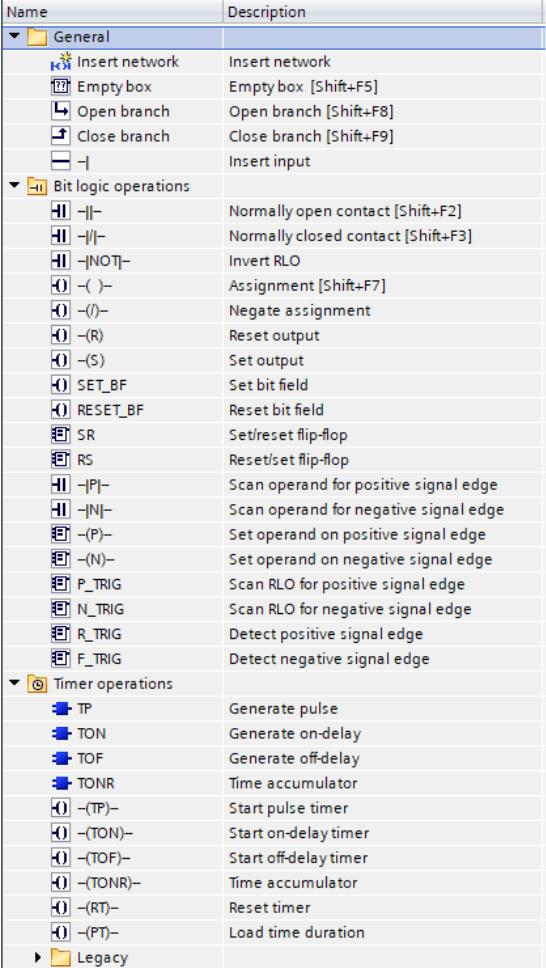
In the standard library, you will find several groups of ladder logic instructions:.
- Bit logic operations
- Timer operations
- Counter operations
- Comparator operations
- Math functions
- Move operations
- Conversion operations
- Program control operations
- Word logic operations
- Shift and rotate
In this document, you will find explanations of some instructions, which will serve as your first step into the programming world!
Ladder Logic Basics
Much like computers, PLCs operate using binary signals (on or off states). In programming terms, this is known as a boolean, which can only have two possible values.
A single bit in memory, which can be set to 0 or 1, is used in most basic PLC instructions. The PLC runs the program one rung at a time. As it processes each rung, the PLC reads the instructions on the left and checks if the logic is set to TRUE. The logic is TRUE when a hypothetical current can pass through the instructions. Each instruction comes with conditions that determine whether it evaluates to TRUE or FALSE.
Now, let’s discuss two of the most basic Ladder Logic instructions used in TIA Portal: Normally Open (NO) contact and Normally Closed (NC) contact.
- Normally Open (NO) contact: This input instruction checks the value of a specific boolean bit. If the bit is set to 1 (HIGH), the contact closes, and the condition evaluates to TRUE, allowing the current to pass through. If the bit is set to 0 (LOW), the contact remains open, and the condition evaluates to FALSE.
- Normally Closed (NC) contact: This input instruction behaves inversely to the NO contact. If the bit is set to 0 (LOW), the contact closes, and the condition evaluates to TRUE. If the bit is set to 1 (HIGH), the contact opens, and the condition evaluates to FALSE.
These basic instructions are essential for controlling the flow of logic in Ladder Logic programming within TIA Portal.
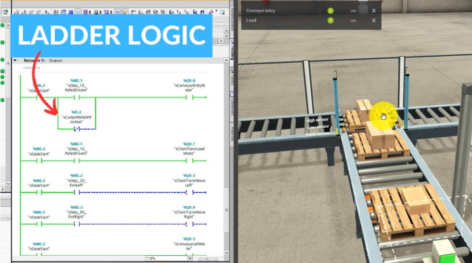
Let’s analyze a basic scenario with a push button and a conveyor.

The ladder logic shown in the image demonstrates the principle of operation for a conveyor system controlled by a pushbutton input.
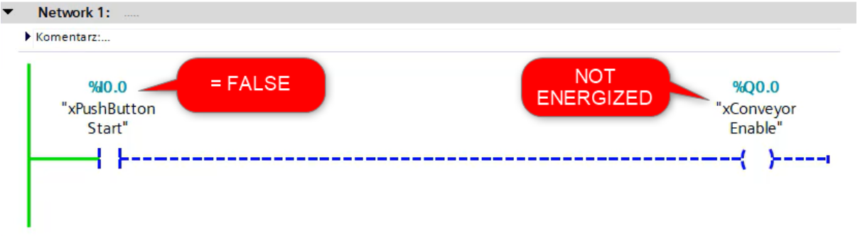
PLC Cycle 1 (Button Not Pressed – FALSE Condition):
- Input Condition: In the top network, the pushbutton (%I0.0, labeled “xPushButton Start”) is in an unpressed state, meaning the input is FALSE (0).
- Logic: The Normally Open (NO) contact associated with the pushbutton is not closed because the input is FALSE. Therefore, no current can pass through the rung.
- Output Condition: The output coil (%Q0.0, labeled “xConveyor Enable”) remains NOT ENERGIZED. The conveyor is not running in this cycle.
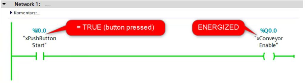
PLC Cycle 2 (Button Pressed – TRUE Condition):
- Input Condition: In the bottom network, the pushbutton (%I0.0, “xPushButton Start”) is now pressed, making the input condition TRUE (1).
- Logic: The NO contact closes because the input is now TRUE, allowing current to flow through the rung.
- Output Condition: The output coil (%Q0.0, “xConveyor Enable”) becomes ENERGIZED, activating the conveyor in this cycle.
Summary:
- When the button is not pressed (%I0.0 = FALSE), the output (%Q0.0) remains de-energized, and the conveyor does not operate.
- When the button is pressed (%I0.0 = TRUE), the output (%Q0.0) is energized, and the conveyor is activated.
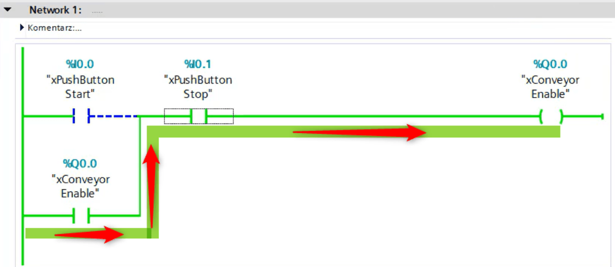
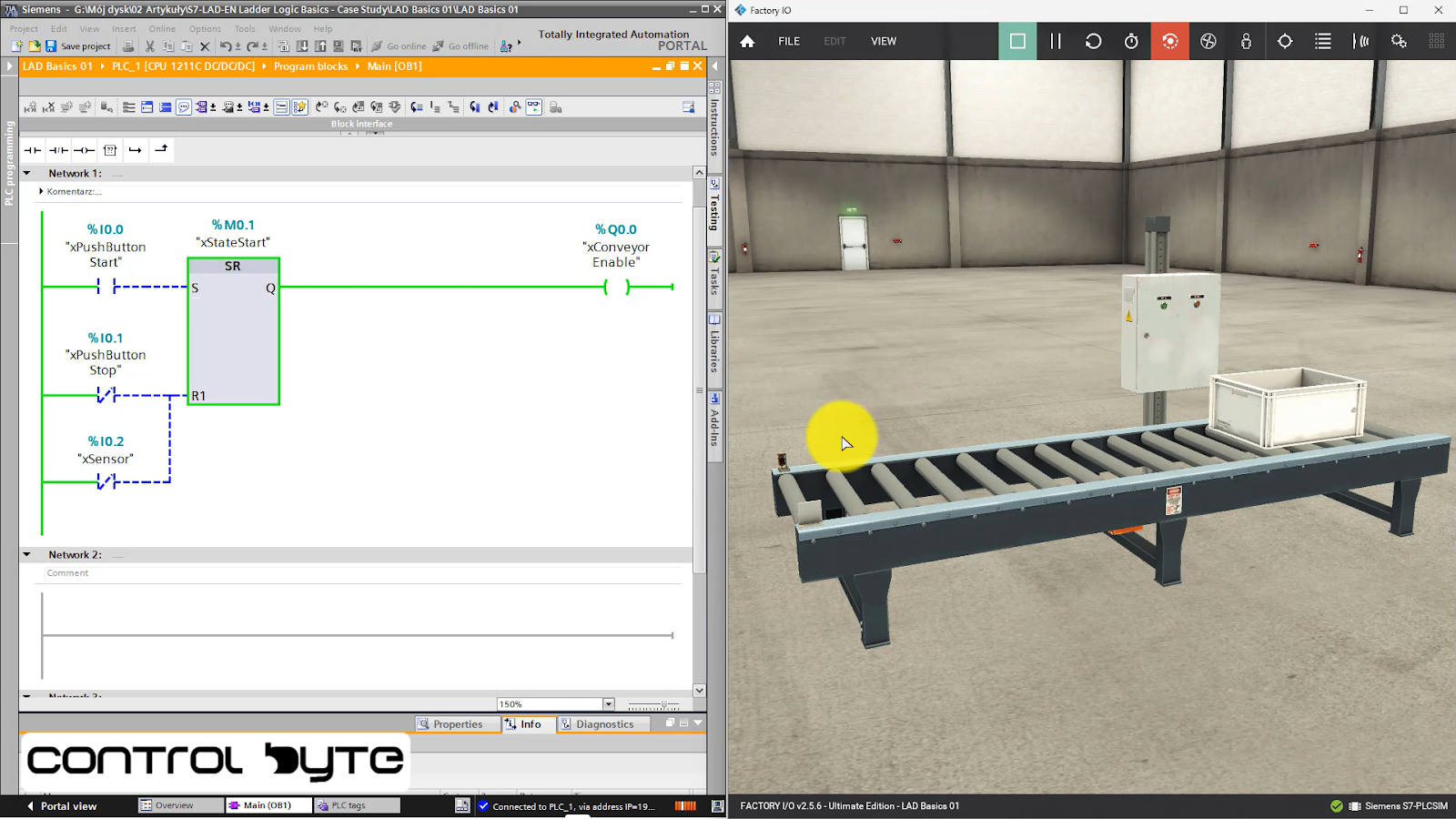
Ladder Logic Structure
Now that we’ve looked at a basic example demonstrating how a single ladder logic rung works, it’s time to talk about circuit branches. Circuit branches allow the current to flow through alternative paths as the rung is executed. While the instructions are still processed in the same way, we need to consider the different routes the current can take.
Constructing ladder logic involves creating a series of conditions and actions using branches that represent logical operations, such as AND, OR, and XOR.
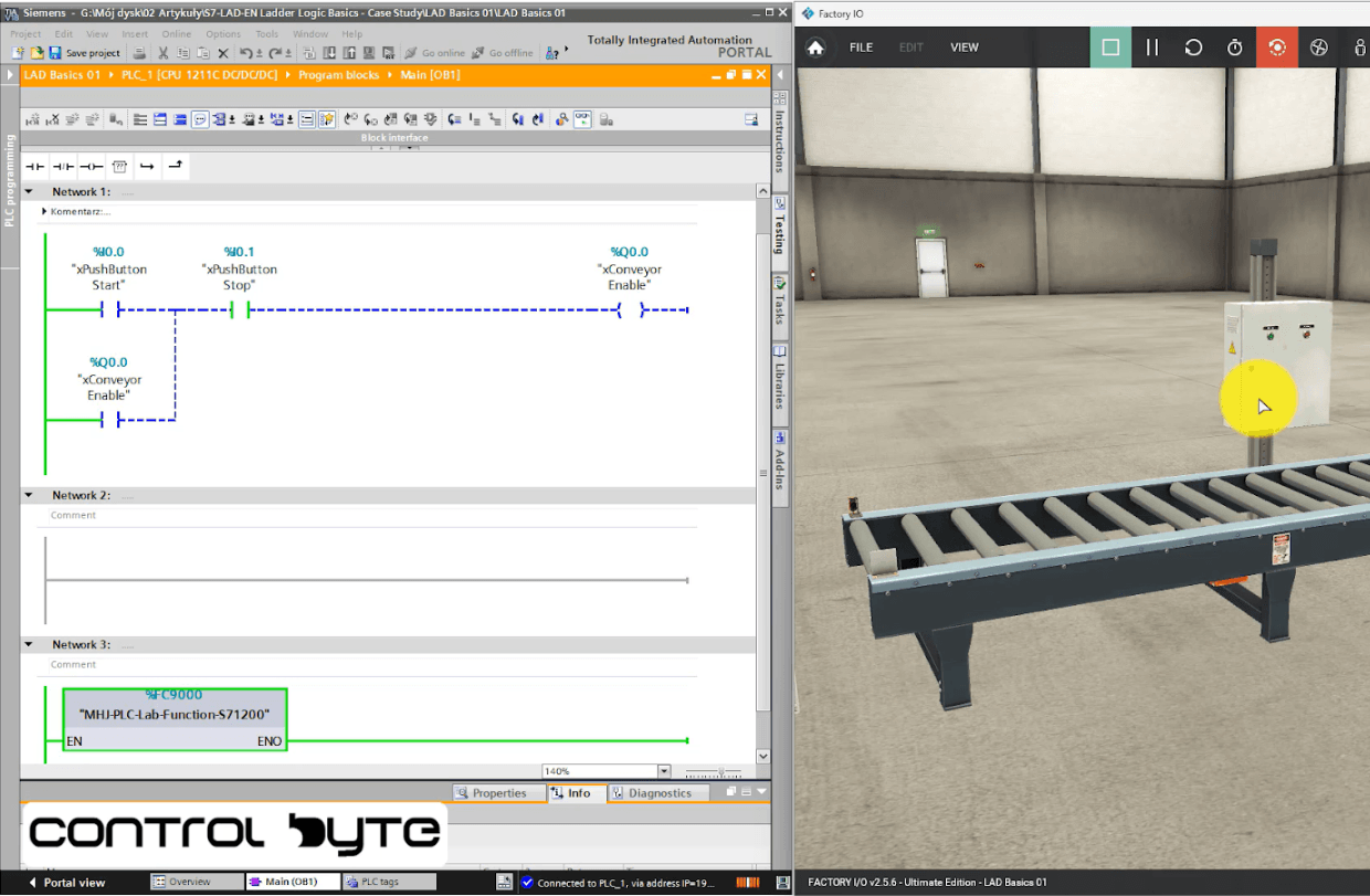
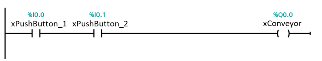
In the example from the picture, you can see how branches are used to control a conveyor system with both start and stop buttons. The logic creates an OR condition by requiring both the “xPushButton Start” to be pressed (normally open contact) OR the feedback from the output coil (“xConveyor Enable”) to stay energized for the conveyor to remain ON.
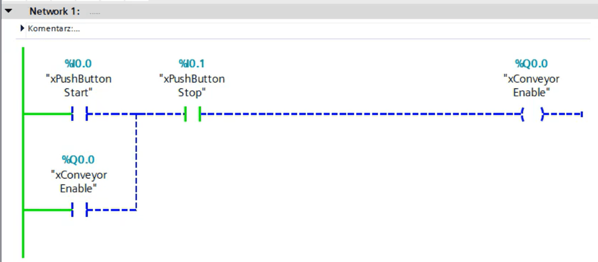
At the same time, the physically normally closed stop button (“xPushButtonStop”) introduces an AND condition, where if it’s pressed, it interrupts the feedback loop, halting the conveyor. By creating branches, ladder logic allows for simultaneous control of multiple conditions, simulating the behavior of digital logic gates. For example, you can add more complexity with additional inputs to create an XOR operation, where one input or another, but not both, would activate the output.
Each branch in ladder logic functions as a path through which the current (or logic signal) must flow, and the current can pass through one or more conditions depending on the logical structure.
Here, the Start Button energizes the coil.
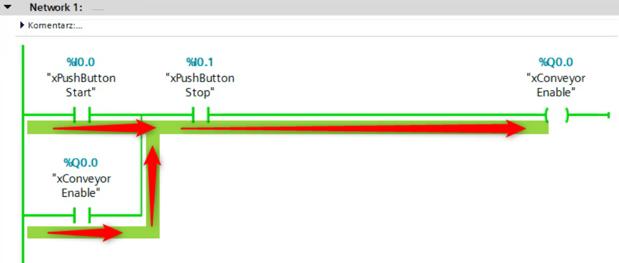
Here the xConveyorEnable variable, assigned to NO contact in parallel to Start Button, energizes the coil. It is called latching circuit.
If you want to learn more, check videos how this system operates:
Basic Ladder Logic Symbols
Bit logic operations – NO contact
Contact NO – Normally Open
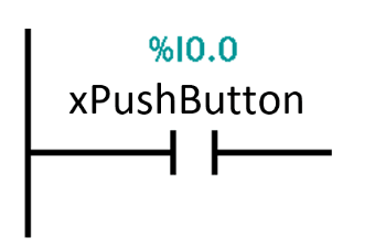
Normally Open contact is closed („conducts signal”), when the operand has a signal state of “1“ – %I0.0 has a signal state of TRUE / 1
Normally Open contact is open („doesn’t conduct signal”), when the operand has a signal state of “0“ – %I0.0 has a signal state of FALSE / 0

Logical operation AND
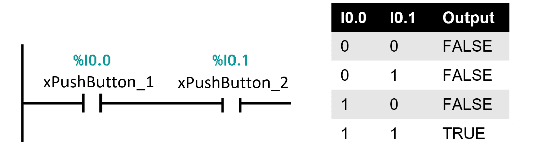
Logical operation OR

Bit logic operations – NC contact
Contact NC – Normally Closed
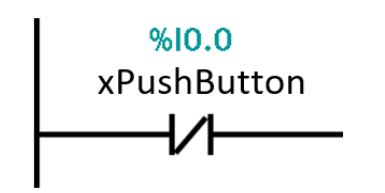
Normally Closed contact is closed („conducts signal”), when the operand has a signal state of “0“ – I0.0 has signal state of FALSE / 0
Normally Closed contact is open („doesn’t conduct signal”), when the operand has a signal state of “1“ – I0.0 has signal state of TRUE / 1
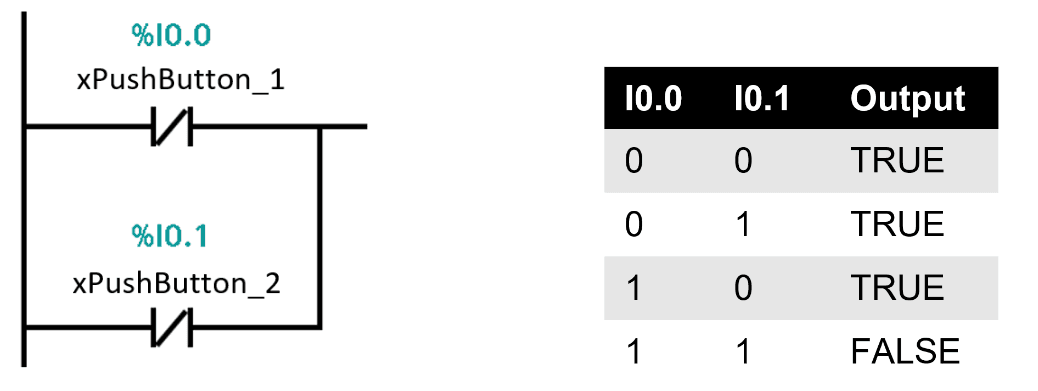
Logical operation NOR
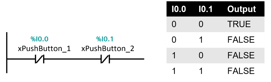
Logical operation NAND
Bit logic operations – Assignment (coil)
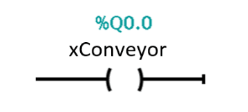
Coil – instruction writes a value for specified operand.
Sets TRUE / 1 when state before the instruction in the branch (RLO) is TRUE / 1.
Sets FALSE / 0 when state before the instruction in the branch (RLO) is FALSE / 0
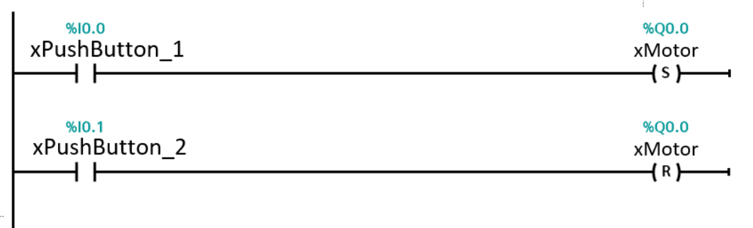
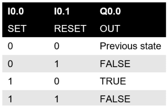
Bit instructions– SET/RESET
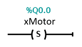
If coil S (SET) is active, sets the state of the assigned variable to TRUE / 1.
If coil S (SET) is not active, the state of the assigned variable is not changed by this instruction.
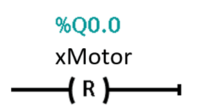
If coil R (RESET) is active, it sets the state FALSE / 0 of the assigned variable.
If coil R (RESET) is not active, the state of the assigned variable is not changed by this instruction.
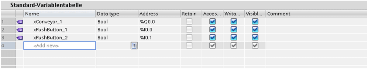
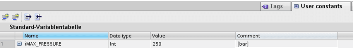
Variables and variable types
In PLC programming, variables and constants are essential for managing signals and data. A variable is a named memory location whose value can change during program execution. It allows the system to respond dynamically to inputs, such as sensor data or user actions. In contrast, a constant also has a memory address and stores data, but its value remains fixed throughout the program’s runtime, ensuring consistency in critical settings like limits or setpoints.
Variable/constant key features:
- Stores data
- Has name
- Has type
- Has addres in CPU memory
- Variable – changes value while program execution
- Constat – does not change value while program execution
Basic variable types in TIA Portal
| Name | Prefix | Type | Size | Range | Example | |
|---|---|---|---|---|---|---|
| bits | bytes | |||||
| Bool | x | logic | 1 | – | 0, 1 | TRUE |
| Byte | b | Bit string | 8 | 1 | does not have numerical value | 16#F |
| Word | w | Bit string | 16 | 2 | does not have numerical value | 16#F0F0 |
| DWord | dw | Bit string | 32 | 4 | does not have numerical value | 16#FFFFFFFF |
| USInt | usi | integer | 8 | 1 | 0… 255 | 78 |
| UInt | ui | integer | 16 | 2 | 0… 65 535 | 65265 |
| UDInt | udi | integer | 32 | 4 | 0… 4294967295 | 24891924 |
| SInt | si | integer | 8 | 1 | -128… 127 | -50 |
| Int | i | integer | 16 | 2 | -32 768… 32 767 | 23562 |
| DInt | di | integer | 32 | 4 | -2 147 483 648…2 147 483,647 | -2131754992 |
| Real | r | Floating point | 32 | 4 | -3.402823e+38… -1.175 495e-38, ±0, +1.175 495e-38…+3.402823e+38 | 123.456 -3.4 |
| Char | ch | Character | 8 | 1 | ASCII table | ‘H’ |
| String | s | Character string | 256 | 0…254 | ‘Example string’ | |
| Data | date | 16 | 2 | D#1990-1-1…D#2168-12-31 | D#2014-02-10 | |
| Time | tim | 32 | 4 | T#-24d_20h_31m_23s_648ms…T#24d_20h_31m_23s_647ms | T#5m_30s T#1d_2h_15m_30s_45ms TIME#10d20h30m20s630ms | |
| Time_of_day | tod | 32 | 4 | TOD#0:0:0.0 to TOD#23:59:59.999 | TOD#10:20:30.400 TIME_OF_DAY#10:20:30.400 | |
| DTL | dt | 12 | Min.: DTL#1970-01-01-00:00:00.0 Max.: DTL#2554-12-31-23:59:59.999 999 999 | DTL#2008-12-16-20:30:20.250 | ||
| Void | empty | 0 | 0 | |||
Interview Practice Projects and Questions
Below you will find the most common interview questions. Remember, your interviewer doesn’t have the entire day for you to program a production line. It will be a 10-minute task at most!
- How would you program a start/stop motor control circuit using ladder logic? Walk through the steps for programming a basic motor control circuit using ladder logic.
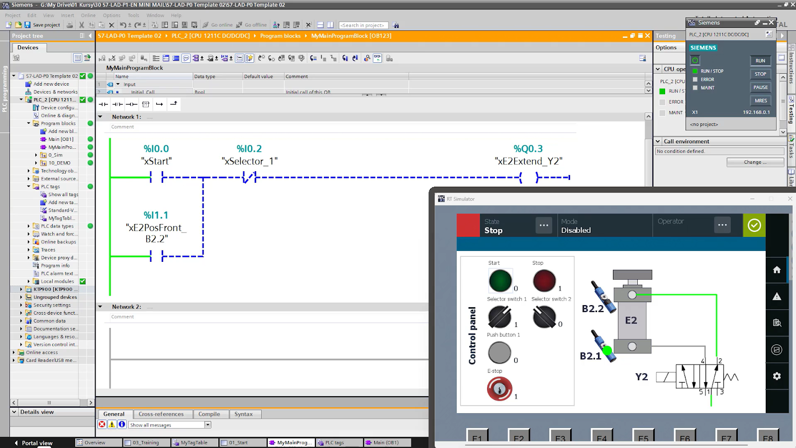
- How would you program a pneumatic actuator with 2 sensors and a 5/2 valve? Explain the steps to control the movement of the pneumatic actuator using the sensors and valve in ladder logic or another PLC programming language.
- How would you program a water tank control system with 2 level switches and a pump? Describe how you would use ladder logic or another programming method to manage water levels using the switches to control the pump.
- Describe the different variable types used in TIA Portal. Provide details on the variable types available in Siemens TIA Portal, such as global, local, and instance variables, and their uses.
- What are the program blocks available in TIA Portal? Explain the different program blocks (like OBs, FBs, FCs, DBs) used in Siemens TIA Portal and their functions.
How would you program a start/stop motor control circuit using ladder logic?
Solution: https://controlbyte.tech/blog/ladder-logic-basics-conveyor-programming/
How would you program a pneumatic actuator with 2 sensors and a 5/2 valve?
Solution:
- Lesson #1: Siemens S7-1200 PLC Programming Free Course (link)
- Lesson #2: Basic instructions of Ladder Logic – NO/NC contacts, AND, OR operations (link)
- Lesson #3: Pneumatic cylinder operation, Code with latching relay (link)
- Lesson #4: Program sequential operation of pneumatic cylinder (link)
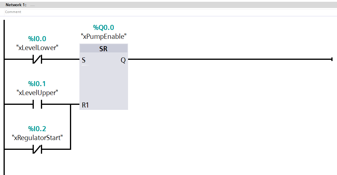
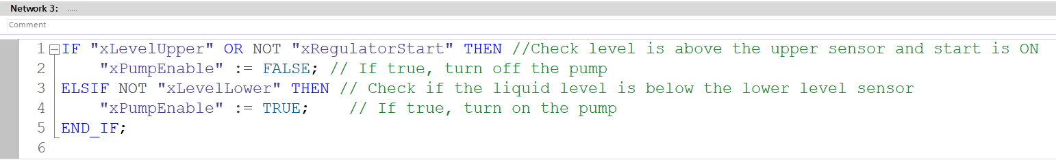
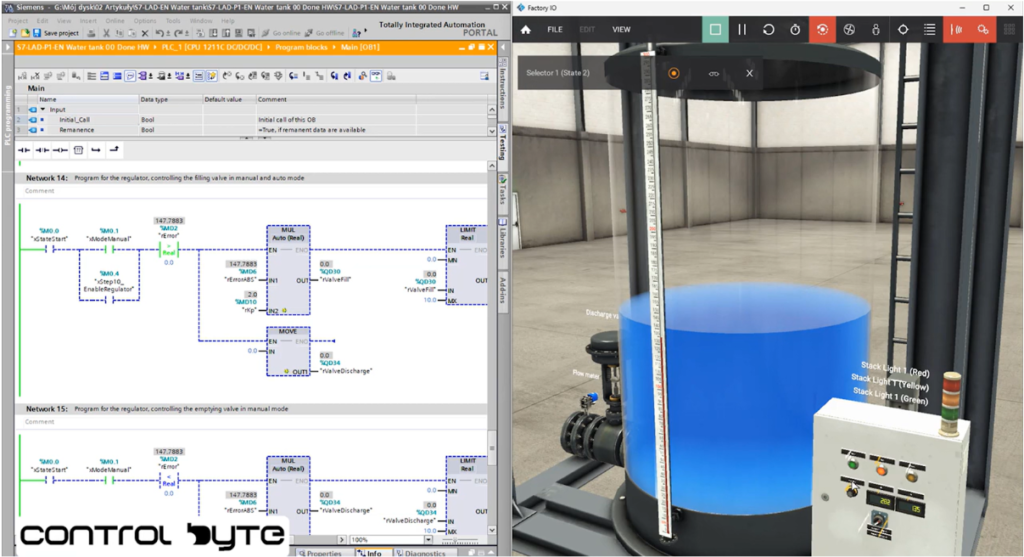
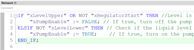
How would you program a water tank control system with 2 level switches and a pump?
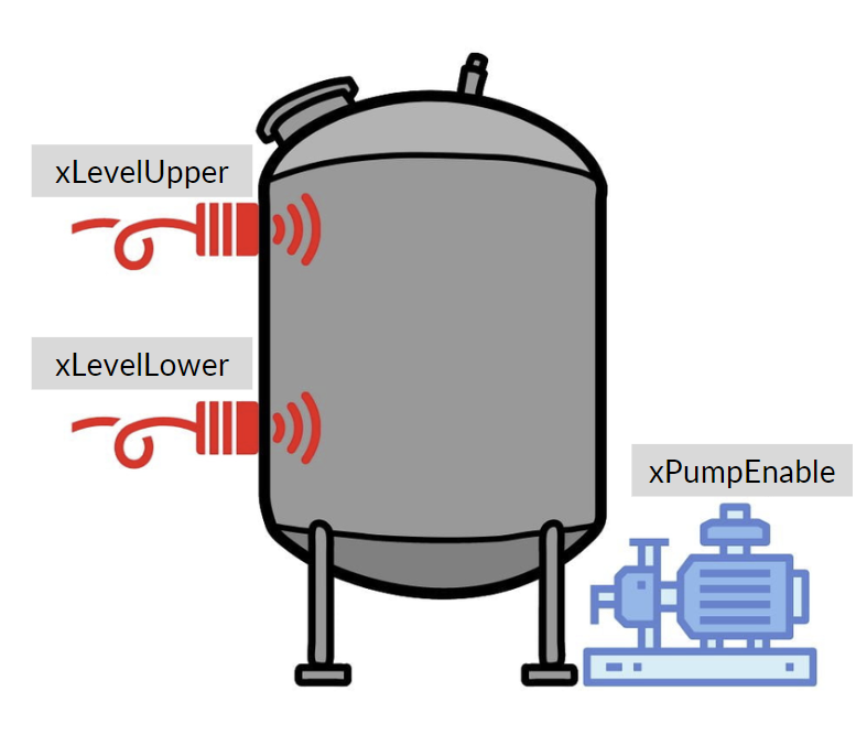
In this code:
- xLevelLower is the lower level sensor.
- xLevelUpper is the upper level sensor.
- xPumpEnable controls the pump. If the liquid level falls below the lower sensor, the pump is turned on (TRUE). If the liquid reaches the upper sensor, the pump is turned off (FALSE).