Today we are going to program a regulator for a water tank in Factory IO. We will implement this code in Ladder Logic within TIA Portal.
TIA Portal provides a ready-to-go block for the PID controller. Sure, we can use it, but the best way to learn how the controller works will be to program such a controller from scratch!
You may think that programming such a controller is impossible—no worries! We will show you how to create code for a PID Controller step by step—it’s a piece of cake!
Variables mapping 🤓
| Variable name | Type | Address |
| rValveFill (0-10.0 V) – part of u(t) | Real | %QD30 |
| rValveDischarge (0-10.0 V) – part of u(t) | Real | %QD34 |
| rSensorWaterLevel (0-10.0 V) – y(t) | Real | %ID30 |
| rSetpoint (0-10.0 V) – r(t) | Real | %ID38 |
Our water tank is equipped with a proportional filling valve, which means you can control the water flow entering the tank. A value of 0 indicates that the valve is set to be closed, and a value of 10.0 signifies that it is fully open. Any value between 0 and 10.0 will partially open the valve. This is simulated by a signal ranging from 0 to 10.0 V in Factory IO. In real life, it could be an analog output signal that controls the proportional valve.
At the bottom of the water tank you can find discharge valve that you can use to empty the tank.
A PID controller consists of 3 parts:
- Proportional part
- Integral part
- Derivative part
We will start by creating code for the proportional part—the easiest one to start with.

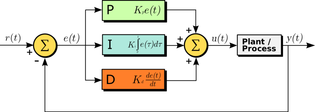
The PID controller diagram depicts how the controller processes an error signal e(t), which is the difference between a reference input r(t) and the process output y(t).
The PID controller comprises three components: the Proportional (P), the Integral (I), and the Derivative (D) parts.
The Proportional part multiplies the error by a constant Kp to form a term that is directly proportional to the error. The Integral part integrates the error over time, multiplied by a constant Ki, to accumulate past errors and correct steady-state errors. The Derivative part differentiates the error, multiplied by a constant Kd, to predict future errors and add a damping effect. The outputs of these three parts are summed to produce the control signal u(t), which is fed to the plant or process to drive the system output y(t) towards the reference input r(t), thus regulating the process.
Sequential filling 🤓
Here you can find a task for our students in the Siemens PLC training. If you program the functionality of the P (Proportional) regulator, the next task will be to program a sequence for filling and discharging the tank.
When the regulator’s gain is incorrect… 😕
When apllying P regulator you have to adjust Kp factor. For Kp=0,45 our system works fine. But if you assign higer values, it may become unstable. Here you can see behaviour when Kp=2.0
What’s next? 🤓
We are working on the next part of this article series.
Meanwhile… check out our PLC Training in Ladder Logic.


