TIA Portal – A Comprehensive Engineering Tool for Industrial Automation
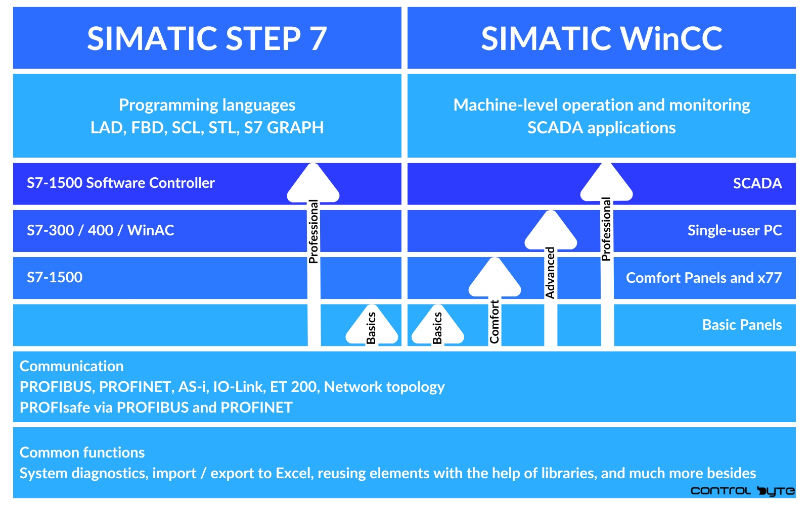
TIA Portal is a software and tool suite developed by Siemens, aimed at integrating multiple development tools for automation devices. It is the result of unifying and modernizing existing solutions such as Simatic Step 7, Simatic WinCC, and Sinamics Starter.
Within the TIA Portal environment, programming, development, and configuration of Siemens PLCs, HMI interfaces, and frequency converters are carried out. The programming logic is based on a block structure, which facilitates the design, maintenance, and diagnostics of industrial machines and processes, provided that an organized and structured approach is followed.
PLC Programming and WinCC Tools
Step 7 is dedicated to programming PLC controllers from the S7-1200, S7-1500, S7-300, and S7-400 families. Alternative controllers for industrial PCs include WinAC and the modern S7-1500 Software Controller. Available programming languages include LAD (Ladder Diagram), FBD (Function Block Diagram), SCL (Structured Control Language), STL (Statement List), and S7 GRAPH.
Developing HMI screens in WinCC is used in supervisory computer-based systems (SCADA) as well as on operator panels from the Basic, Comfort, and Mobile series. Communication between devices supports protocols such as Profibus, PROFINET, and AS-I (Actuator Sensor Interface). It is also worth mentioning the CM communication modules, which enable connectivity using various industrial protocols, such as Modbus and CANOpen.

PLC Programming Structure
Programming PLCs in TIA Portal is based on an architecture divided into blocks:
- OB (Organization Blocks)
- FC (Functions)
- FB (Function Blocks)
- DB (Data Blocks).
Monitoring the system status and controlling actuators is carried out through devices connected to the controller hardware. The PLC’s operating system acts as a translator, interpreting the algorithms.

Organization Blocks and Their Role in Program Execution Cycles
Organization Blocks (OB) are closely tied to program execution cycles and interrupts. Their execution depends on predefined triggers, such as time intervals or the detection of a hardware failure. OB1, the main program block, plays a key role in initialization and in sequentially scanning the calls of other blocks containing implemented code. Unlike other OBs, OB1 is executed cyclically and continuously.

According to the presented representation, program execution starts with the contents of OB1 in a linear and synchronous manner, processing instructions from left to right and from the beginning to the end of the block. Once OB1 has finished, the controller’s processor (CPU) resumes execution of the code from the start, and this process repeats indefinitely.
Although the user can create multiple functions (FC) and data blocks (DB), the PLC controller only executes those instructions that have been programmed in OB1 in a specified order. Subroutines are created through block calls, which can be nested.

Interrupts and Program Cycle Time
Because the reproduction of instructions in the main OB1 function depends on processing all assigned functions, the cycle time may vary depending on the plant’s condition and unforeseen programming conditions. To avoid logical errors or to guarantee cyclical execution at a specified time interval, the use of cyclical interrupt blocks is recommended.
Cyclic Interrupt blocks are also executed cyclically, but with a predetermined time interval between subsequent executions.

For example, every 100 ms, the current processing is interrupted so that the instructions contained in the cyclic interrupt block can be executed. This allows for timely and regular processing of selected operations, regardless of the state of the main program cycle.
Functions (FC) in TIA Portal
Functions (FC) are used to compress algorithms and return values to output-defined variables in accordance with the input parameters and the operations performed within the block.

Local variables declared in FC functions can have various characteristics, such as:
- In (Input): Input parameters of the function. It is crucial to distinguish the states of different calls of the same function.
- Out (Output): Output parameters of the function. Differentiating the actions of various calls of the same function is important.
- InOut (Input/Output): Parameters that serve as both input and output simultaneously. This is useful for minimizing errors resulting from writing to input parameters.
- Temp (Temporary): Temporary variables that are allocated to a random area of the CPU’s memory at the start of the block and overwritten once it concludes. They do not have retention capability or a global reference.
- Constant: Temporary variables with constant values defined at the time of their declaration.
The Use of FC Functions
FC functions allow for organizing and simplifying algorithms, which improves code readability and facilitates code reuse. Their use is particularly beneficial when designing complex processes that require precise control over input, output, and temporary variables.
Function Blocks (FB) in TIA Portal
Function Blocks (FB) have a structure and functions similar to Functions (FC), with one key difference the ability to create instance data blocks (iDB) linked to each FB call. This ensures that each FB call is assigned a unique memory space, allowing for individual data management for every invocation.

Function Blocks allow the declaration of variables similar to those in FC blocks. The available variable types are:
- Input (In): Parameters passed into the block to provide the data needed for its operation.
- Output (Out): Parameters that return the result of the block’s operation.
- Input/Output (InOut): Parameters that can act as both input and output, useful for operations requiring modification of input data.
- Temporary (Temp): Variables used only during the execution of the block. They are removed once the block’s operation is complete and do not support retention.
- Static (Static): This is an additional type of variable available in FB blocks. Static variables are stored in the CPU’s non-volatile memory and retain their values after the block’s execution is finished. They can therefore be utilized globally and referenced at any point in the program.
For example, if we create a function block named “Motors” and call it in two different places within the program, each call will be associated with a unique instance data block (iDB). This allows for independent storage and retrieval of data. Suppose the variable Motor_On represents the state of a motor. In this case:
- Motor A can be assigned to data block DB1, storing a unique state associated with that particular call.
- Motor B will be linked to DB2, and its state will be stored separately.

This structure allows the same algorithm to be used multiple times in different parts of the program without the risk of overwriting data or variable collisions.
Advantages of Function Blocks
Function Blocks in TIA Portal offer several benefits, such as:
- Memory Separation: Each FB call has a dedicated memory space, allowing for independent data management.
- Code Reuse: The same block can be called multiple times in the program, which significantly simplifies its structure.
- Data Retention: Thanks to static variables, FB blocks allow the preservation of variable values even after they have finished executing.
Practical Use of Function Blocks allows for a clearer, more flexible, and efficient organization of control programs in the TIA Portal environment.
Understanding User-Defined Data Types (UDT) in TIA Portal
In TIA Portal, in addition to standard data types like Integer, Real, or Boolean, you can use User Data Types (UDT) – user-defined data structures. UDTs allow for creating flexible and complex structures that can consist of any combination of existing data types and arrays.
The use of UDTs significantly improves data organization in the program, enabling easy replication of repeatable structures. This makes application development faster and diagnostics clearer. For example, instead of declaring separate variables for each motor, you can create a Motor_Data structure containing parameters such as ID, Operating Status, and Speed.
UDTs enhance code readability and save time by allowing the reuse of the same structures in different parts of the program.
Summary
TIA Portal is a versatile engineering environment that integrates tools for programming and configuring industrial automation devices. With support for PLC controllers, HMI interfaces, and frequency converters, it allows for effective system design and diagnostics. The structure based on functional blocks (OB, FC, FB) ensures flexibility and consistency in programming, and instance data blocks (iDB) enable memory management for each block invocation.
Additionally, user-defined data types (UDT) allow for the organization and reuse of complex data structures, significantly facilitating work on intricate projects. TIA Portal supports various programming languages and communication protocols, making it an indispensable tool in modern industrial automation.


