For Beginner PLC Users
For those just starting with PLC systems, I recommend first becoming familiar with combinational logic. Combinational logic will help you understand how to combine two logic states – TRUE and FALSE. With the basics of combinational logic, you can write your first PLC program.
A PLC program utilizes logic that, in mathematics, is known as Boolean algebra. In Boolean algebra, values can only be TRUE or FALSE. In PLC controllers, TRUE and FALSE are represented by 0 and 1. When programming controllers, you need to switch to “binary thinking.”
In this article, I’ll use simple electrical schematics to analyze logical concepts.
Logic with Simple Examples
The simplest example involves a light bulb and two normally open switches. These two basic elements share an important characteristic: both operate in two states – the light bulb is either on or off, and the switch is either closed or open.
You can connect the light bulb and switches in several ways.
The first option is a series connection.

When two switches connect in series, the light bulb turns on only if both switches are engaged. In Boolean logic, this represents the AND function. We assume a switch is in a TRUE state when it’s closed and a FALSE state when it’s open. The same applies to the light bulb – if it’s on, its state is TRUE; if it’s off, its state is FALSE.
Combinational Logic and Six Logic Gates
Let’s go back to the AND logic function mentioned earlier. The AND function is a way of determining the output state.
AND Gate
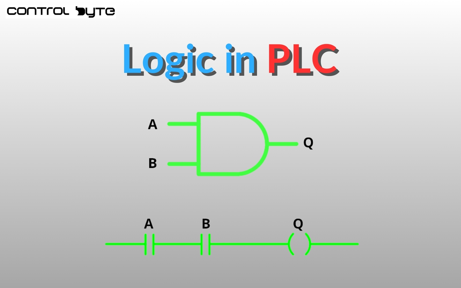
All Boolean logic gates have inputs and outputs. The output state depends on the input states. To set an output to high (TRUE) using the AND gate, you must set all inputs to high (TRUE). In our example above, the two switches are inputs, and the light bulb is the output. In this case, the light bulb will turn on when both switches are engaged. Here’s the symbol for an AND gate:

The standard names and symbols for AND gate inputs are A and B, with Q representing the output. This gate always has two inputs and one output, though it can be expanded to accommodate more inputs but still has only one output.
The input and output states can be illustrated with a truth table, as follows:
| A | B | Q |
| False | False | False |
| True | False | False |
| False | True | False |
| True | True | True |
With this truth table, you can analyze how the output behaves based on the input states.
Below is a table to help you understand terminology in logic for various cases:
| Switch State | Boolean Algebra | PLC Program Logic |
| On | FALSE | 0 |
| Off | TRUE | 1 |
OR Gate
Parallel connections work differently from the series connection discussed previously. Here, each switch has a direct connection to the light bulb, meaning any switch can turn the light bulb on. Below is the symbol for an OR gate:

Like the AND gate, which we learned about earlier, the OR gate has two inputs and one output. The input symbols are A and B, with the output labeled Q.
The OR gate’s operation is illustrated with a truth table:
| A | B | Q |
| 0 | 0 | 0 |
| 0 | 1 | 1 |
| 1 | 0 | 1 |
| 1 | 1 | 1 |
The OR gate output goes high (TRUE) when at least one input is high (TRUE).
The formula A + B, or A ∨ B, also represents this gate. We refer to this as logical alternation.
NOT Gate – Logical Negation
There are five basic logic gates in Boolean logic that you should know. I will now describe the NOT gate (logical negation).

The NOT gate reverses the input state to the opposite and presents it at the output. For example, when the input is high, the output is low.
The truth table for this looks as follows:
| A | Q |
| 0 | 1 |
| 1 | 0 |
Normally Open and Normally Closed Contacts
Returning to our example with switches and the light bulb, we can enhance the functionality of our switches. Switches can operate in two different ways: they can either close or break the circuit. These two types of switches are normally open and normally closed.
NAND Gate
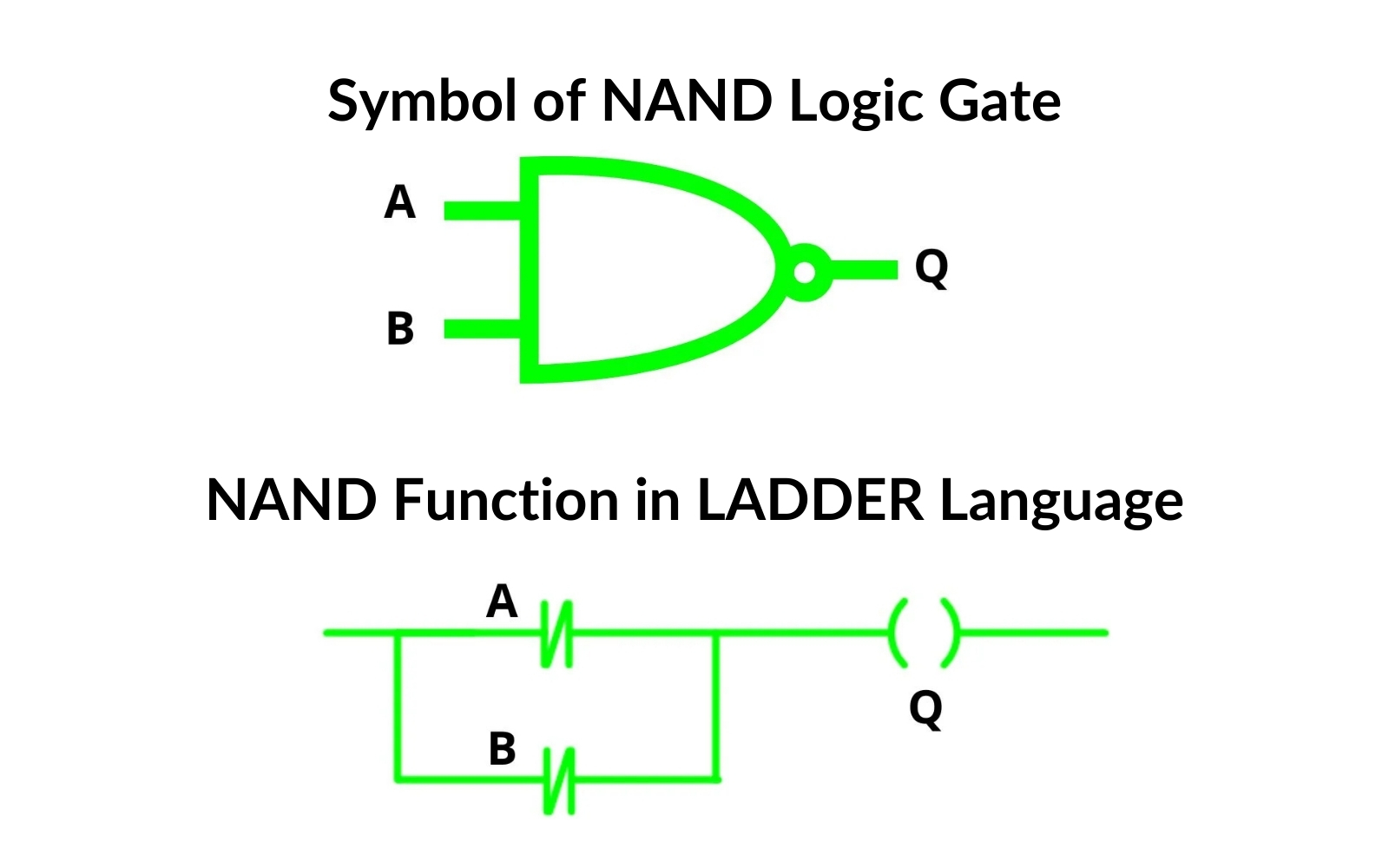
If we take our OR function and negate our inputs using normally closed contacts, we get a NAND function. The light will turn off only when both switches are open.
| A | B | Q |
| 0 | 0 | 1 |
| 0 | 1 | 1 |
| 1 | 0 | 1 |
| 1 | 1 | 0 |
NOR Gate
Negating the inputs of the AND gate using normally closed contacts (NC) results in a NOR function.
| A | B | Q |
| 0 | 0 | 1 |
| 0 | 1 | 0 |
| 1 | 0 | 0 |
| 1 | 1 | 0 |

Combined Gates
By arranging contacts in series-parallel configurations, you can implement additional logic functions such as Exclusive-OR (XOR) and Exclusive-NOR (XNOR).
Exclusive-OR Gate (XOR)
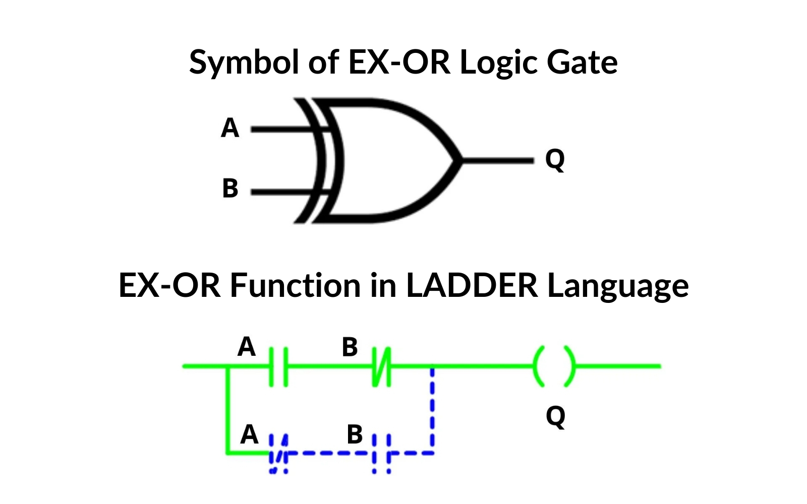
The upper branch in the electrical diagram (contact A (NC) in series with contact B (NO)) corresponds to a NAND gate. The lower branch (contact A (NO) in series with contact B) is also a NAND gate. These two branches (upper and lower) are connected in parallel.
| A | B | Q |
| 0 | 0 | 0 |
| 0 | 1 | 1 |
| 1 | 0 | 1 |
| 1 | 1 | 0 |
Analyzing the presented electrical diagrams and logic functions, you can observe certain analogies:
- Parallel connection of NO contacts performs the OR function.
- Series connection of contacts represents the AND function.
- The normally closed contact is equivalent to the NOT (negation) gate.
Simple Programs in Ladder Logic
With a basic understanding of Boolean logic, you can proceed to programming PLC controllers, for example, using Ladder logic. This graphical language resembles an electrical diagram. Ladder language is available in programming environments such as Codesys or TiA Portal.
Thank you for reading! If you’re interested in learning more, explore our courses for in-depth training: Control Byte Courses.

