Today, we will focus on Ladder Logic, also known as Ladder Diagram (LD), and compare it with other PLC programming languages compliant with the IEC 61131-3 standard.
PLC Programming Languages in the IEC 61131-3 Standard
PLCs are specialized computers designed to monitor and control automation processes. The IEC 61131-3 standard defines five programming languages supported by nearly all PLC manufacturers:
- Ladder Diagram (LD),
- Function Block Diagram (FBD),
- Structured Text (ST),
- Sequential Function Chart (SFC),
- Instruction List (IL).
In this article, we will focus on Ladder Diagram and then compare it with the other programming languages.
What is a Ladder Diagram?
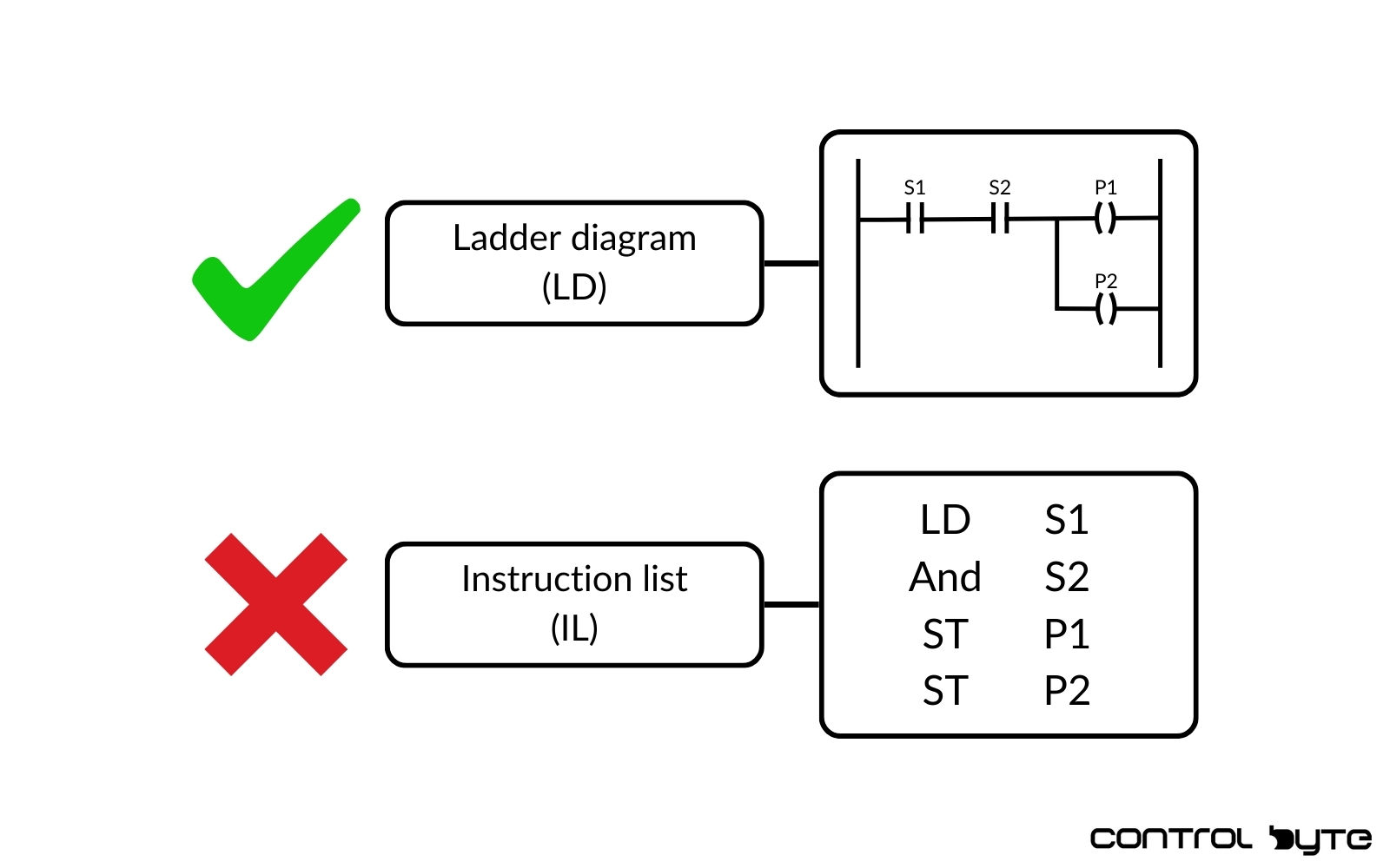
Ladder Diagram is the most popular PLC programming language, primarily because it was the first one introduced. It was developed as an alternative to hardwired relays in control cabinets. Designed with electricians in mind, its appearance resembles electrical schematics.
LD is a graphical programming language, making it very intuitive and easy to debug. It is ideally suited for implementing complex Boolean logic, which is its primary purpose.
An example of LD code controlling a motor clearly illustrates the input conditions that must be met to start the motor. This kind of visualization is one of the reasons why LD is so popular.

Comparison of Ladder Diagram with Other IEC 61131-3 Languages in automation
Programming Ladder Logic vs Structured Text (ST)
Structured Text is a textual programming language preferred by individuals with experience in traditional programming (e.g., Python).
Advantages of Structured Text (ST):
- Allows complex calculations to be written in a single line, whereas in LD, each operation requires separate instructions.
- Supports loops (FOR, WHILE), simplifying repetitive operations.
Recommendation:
ST is ideal for large-scale calculations and data manipulation. However, for the primary language of a project, LD is recommended. Why? LD is more understandable for maintenance personnel, who often are not programmers.

Ladder Diagram vs Function Block Diagram
Function Block Diagram (FBD) is another high-level, graphical programming language used in PLCs.
FBD is particularly popular in the process industry because its visual structure resembles P&ID (Piping and Instrumentation Diagrams), which illustrate the layout and connections of process equipment. This similarity makes it easier for professionals in this sector to adapt to the language.
In practice, the same conveyor control algorithm can be implemented in both Ladder Diagram and Function Block Diagram. The following example demonstrates how these two languages compare in appearance.

Like Ladder Diagram, Function Block Diagram (FBD) is a graphical programming language that is intuitive, easy to understand, monitor, and debug. One of FBD’s key strengths is its facilitation of continuous process control, such as implementing PID loops.
For this reason, Function Block Diagram is recommended in the process industry, particularly in environments where continuous control is standard. Its visual structure and intuitiveness make it better suited for such applications compared to Ladder Diagram.
Outside the process industry, the differences between FBD and LD become less significant. In such cases, the choice between these languages primarily depends on user preferences, company policies, or the standards followed in a specific industrial sector.
FBD is a powerful tool for the right applications, and proficiency in it can be a significant asset for any PLC programmer.

Ladder Diagram vs. Sequential Function Chart (SFC)
Sequential Function Chart (SFC) is another high-level PLC programming language, visually resembling a flowchart.
Thanks to its structure, SFC is an excellent tool for modeling high-level sequential processes. Its visual representation makes it easy to illustrate the stages of a process, making it highly intuitive for creating flow diagrams.
However, due to its very general nature, SFC is not suitable for writing detailed control logic. For instance, in a simple conveyor control task, the logic in SFC might occupy nearly half the screen, whereas the same algorithm could be written as a single line of code in Ladder Diagram.

That’s why SFC should not be directly compared to Ladder Diagram — both languages serve different purposes.
Sequential Function Chart is best regarded as a complementary language. You can use it to model a process at a high level and then implement the detailed control logic using Ladder Diagram. This combination ensures clarity in design and efficiency in implementation.
SFC is ideal for sequential processes requiring a clear depiction of stages, but when paired with Ladder Diagram, it creates a powerful and flexible programming system.

Ladder Diagram vs Instruction List (IL)
Instruction List (IL) is a textual programming language similar to assembly language. Due to its difficulty in writing and debugging, this language has been deprecated.
Recommendation:
Avoid using IL in new projects and opt for LD instead.

Recommendations for Programmable Logic Controller Programmers
Based on the discussed programming languages, here are my recommendations:
- Use Ladder Diagram as the default programming language. It is the most widely used and understood in the industry.
- Consider specific languages for particular cases:
- Function Block Diagram (FBD): Ideal for continuous process control.
- Structured Text (ST): Best for calculations and data manipulation.
- Sequential Function Chart (SFC): Excellent for modeling sequential processes.
Summary
In this article, I introduced all IEC 61131-3 languages, compared their strengths and weaknesses against Ladder Diagram, and suggested when to use each language.
Every PLC programmer should be familiar with all these languages to choose the best tool for a given task. Remember—if you only know one tool, every task might look like a nail!


