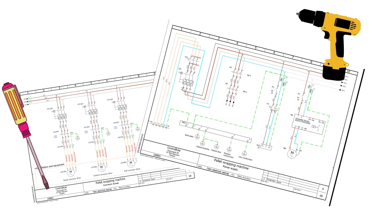
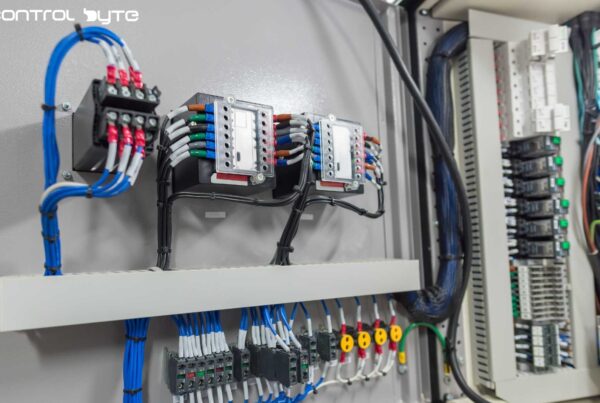
Electrical wiring diagrams are an essential tool for electricians, engineers, and automation technicians. Proper interpretation is crucial for understanding the operation of devices, diagnosing faults, and working safely with electrical installations. Understanding how to read electrical diagrams is the first step toward mastering technical skills in this field.

An electrical diagram is a graphical representation of an electrical system that shows how the components are connected and how the current flows through the system. Examples of such systems include lighting circuits, machine controllers, and even advanced industrial automation systems. In this guide, we will explain how to properly read electrical diagrams, understand symbols, and apply this knowledge in practice.
What is an electrical diagram and why is it important?
An electrical diagram is a map of an electrical system that allows tracking how current flows through a device or installation. It represents both mechanical and electrical elements, such as motors, switches, relays, fuses, and other devices that make up the entire system.
Reading electrical diagrams is crucial for several reasons:
- Diagnostics: When a failure occurs, the diagram helps identify problematic components and understand why a particular part of the system is not working properly.
- Safety: Proper diagram interpretation allows understanding which parts of the system are energized, helping to avoid accidents.
- Design and installation: Electrical diagrams are crucial when installing new electrical systems, as they allow precise placement and connection of components.
Basic elements of an electrical diagram
Each electrical diagram consists of several basic elements represented by graphic symbols. Understanding these symbols is the foundation for reading electrical diagrams.
Wire lines
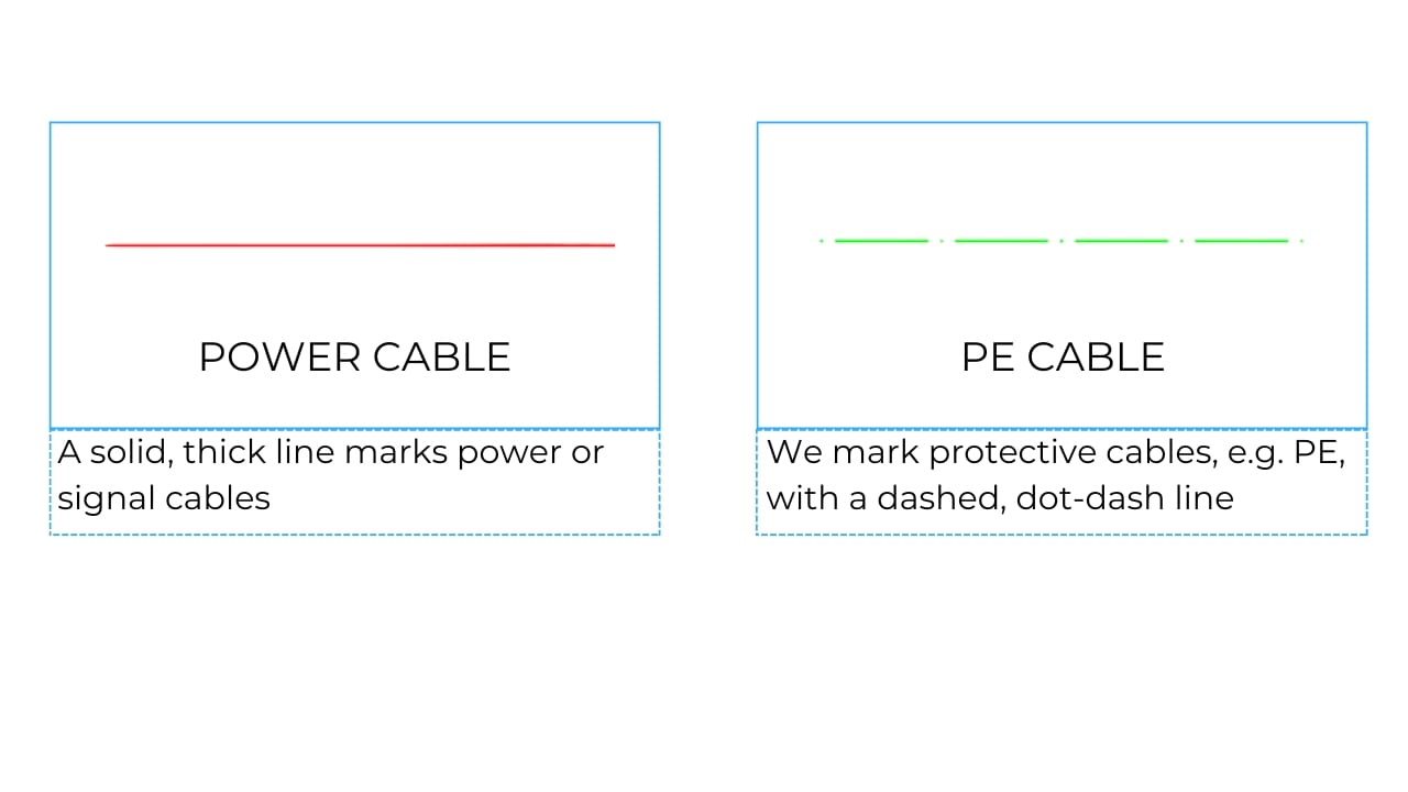
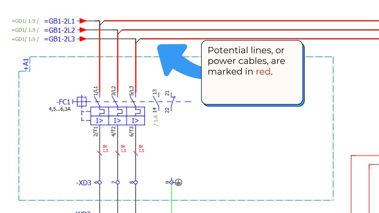
The lines in the diagram represent wires that connect different components. A solid line usually symbolizes power and signal wires, while a dashed line may indicate protective wires (PE).
Nodes and connections
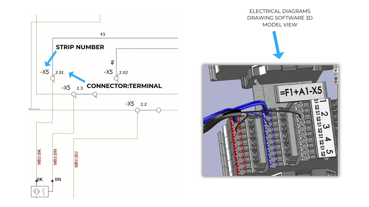
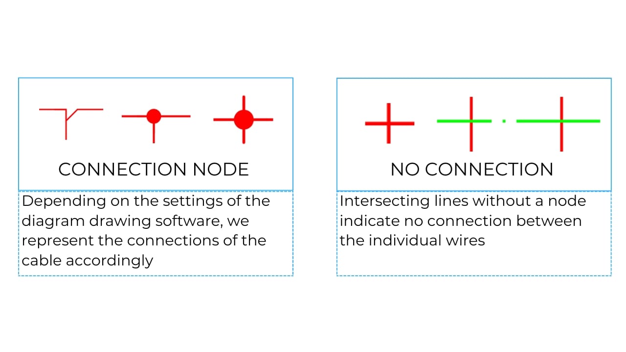
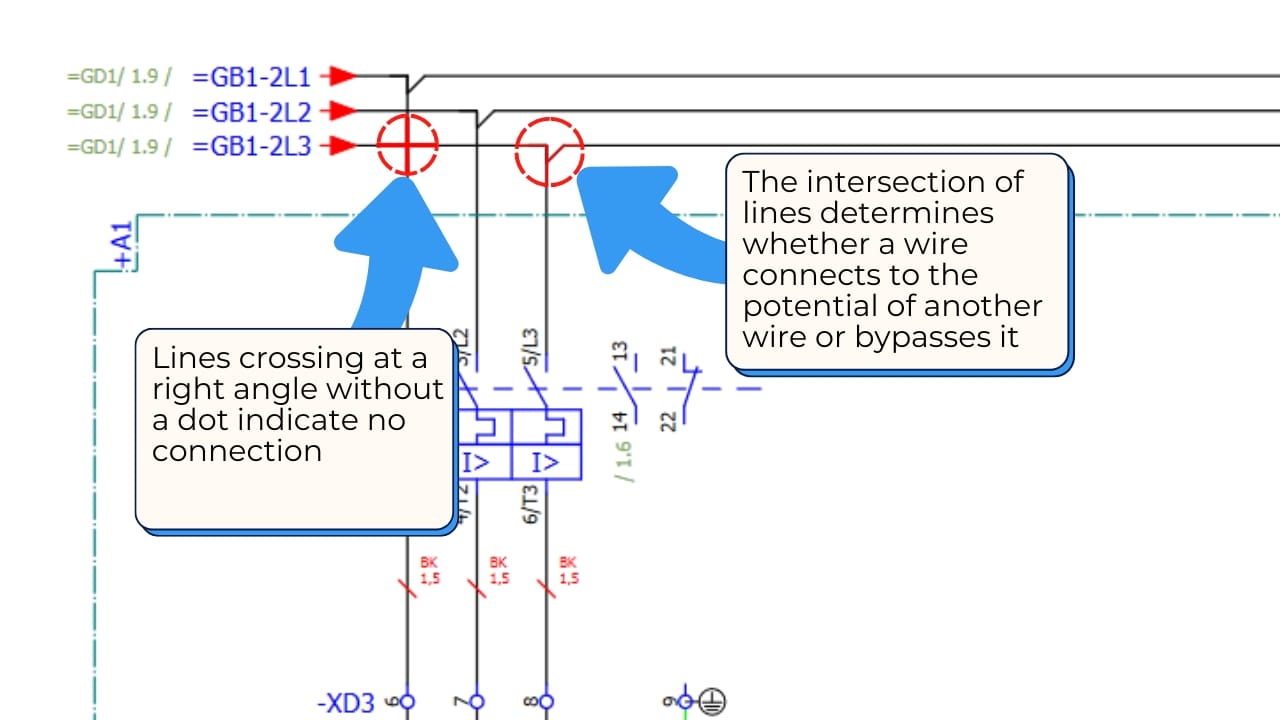
These elements indicate where wires are physically connected. Terminals are crucial as they allow connection of wires, sometimes coming from different parts of the installation.
How to interpret symbols on electrical diagrams?
Every electrical component, such as a switch, fuse, relay, or resistor, has its graphic symbol that makes it easy to identify on the diagram.
Symbols on electrical diagrams are intended to simplify and standardize the way components are represented. This ensures that regardless of the device manufacturer, the person working with the diagram can quickly understand what components they are dealing with.
Here are the most commonly encountered electrical symbols:
| Element | Actual | Symbol |
|---|---|---|
| Push button |  |  |
| Motor switch |  |  |
| Relay |  |  |
| Resistor |  |  |
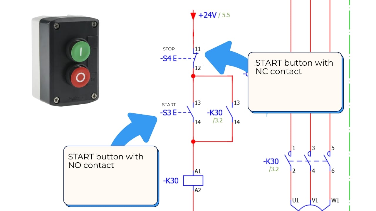
Switch on the diagram
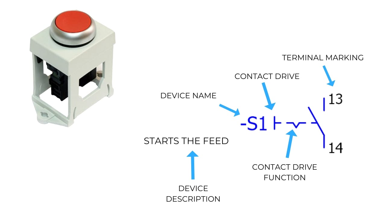
A switch is one of the basic elements controlling an electrical circuit. In diagrams, it is symbolized by a dashed line crossing two connection lines.
Relay on the diagram
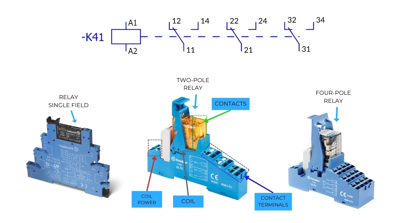
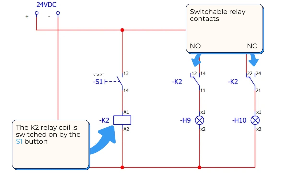
A relay is a component that can open or close an electrical circuit in response to a signal. The relay symbol typically includes both a coil and contacts.
Contactor on the diagram
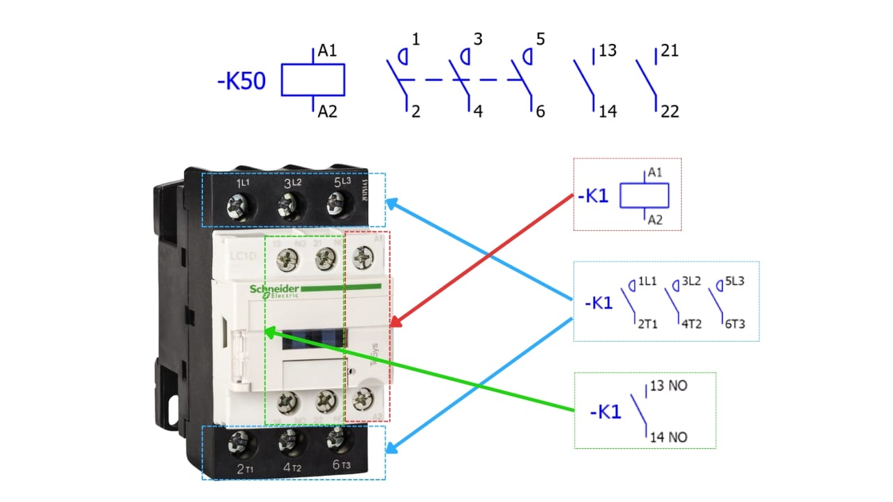
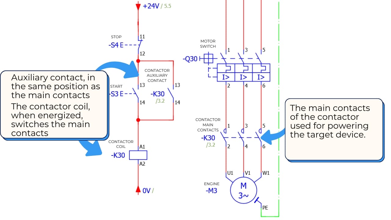
A contactor switches electrical circuits, especially in industrial installations. The diagram symbolizes contactors with a set of contacts and a coil, similar to relays.
Fuses on the diagram
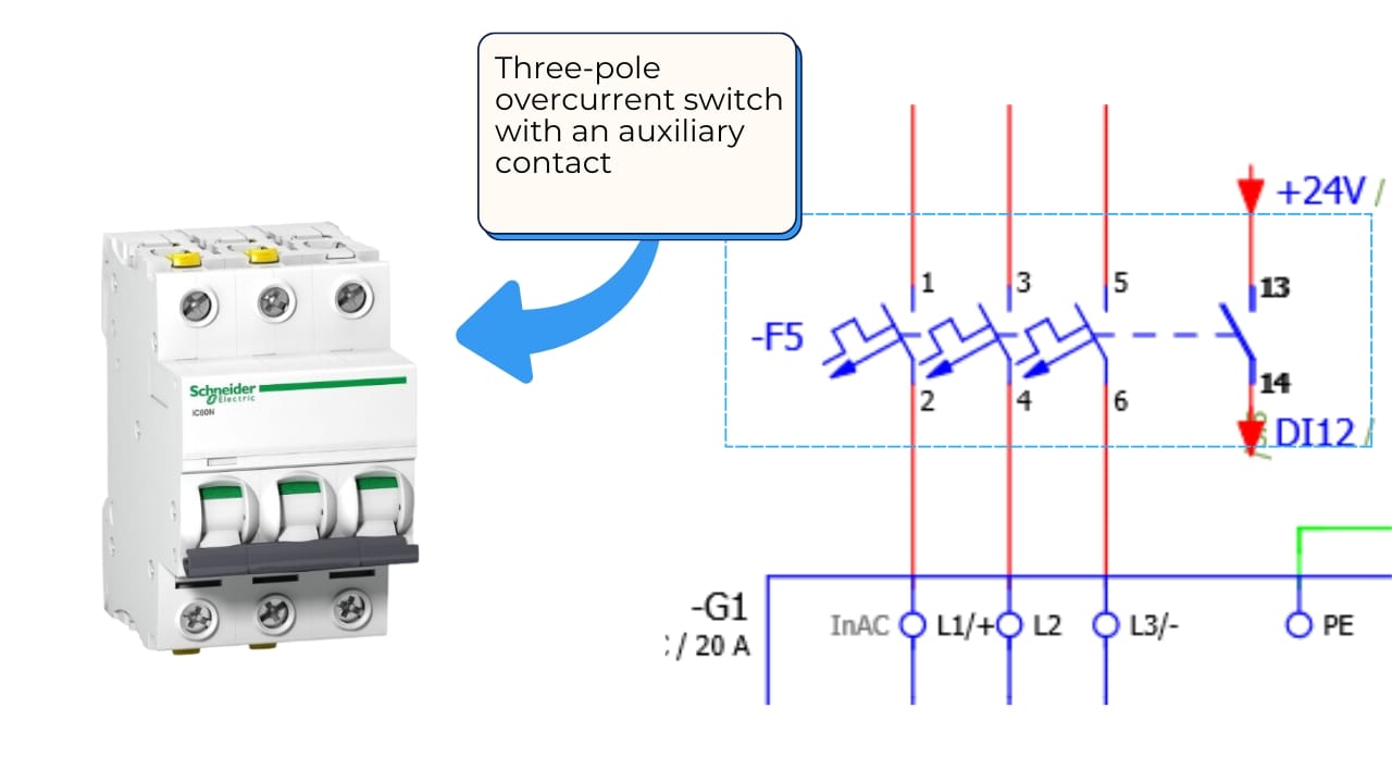
The fuse symbol is a dashed line, indicating that the circuit will be interrupted in case of overload, preventing damage to the installation.
Cross-references and potential lines
Cross-references are markings on diagrams that help locate connections between different pages of documentation. In more complex systems, diagrams often span several pages, with cross-references showing the location of the next part of the connection.

Potential lines, on the other hand, indicate the voltage level in a given circuit. It is important to understand these markings as they can indicate different power levels, e.g., +12V, +24V, or circuit ground (GND). The ability to interpret potential lines is crucial, especially in complex multi-voltage systems.
Practice – how to exercise reading electrical diagrams?
Regular practice is necessary to master the skill of reading electrical diagrams. Start with simple diagrams, such as lighting circuits or basic home installations. Over time, as you gain proficiency, you can move on to more complex projects like industrial automation systems or advanced machine control systems.
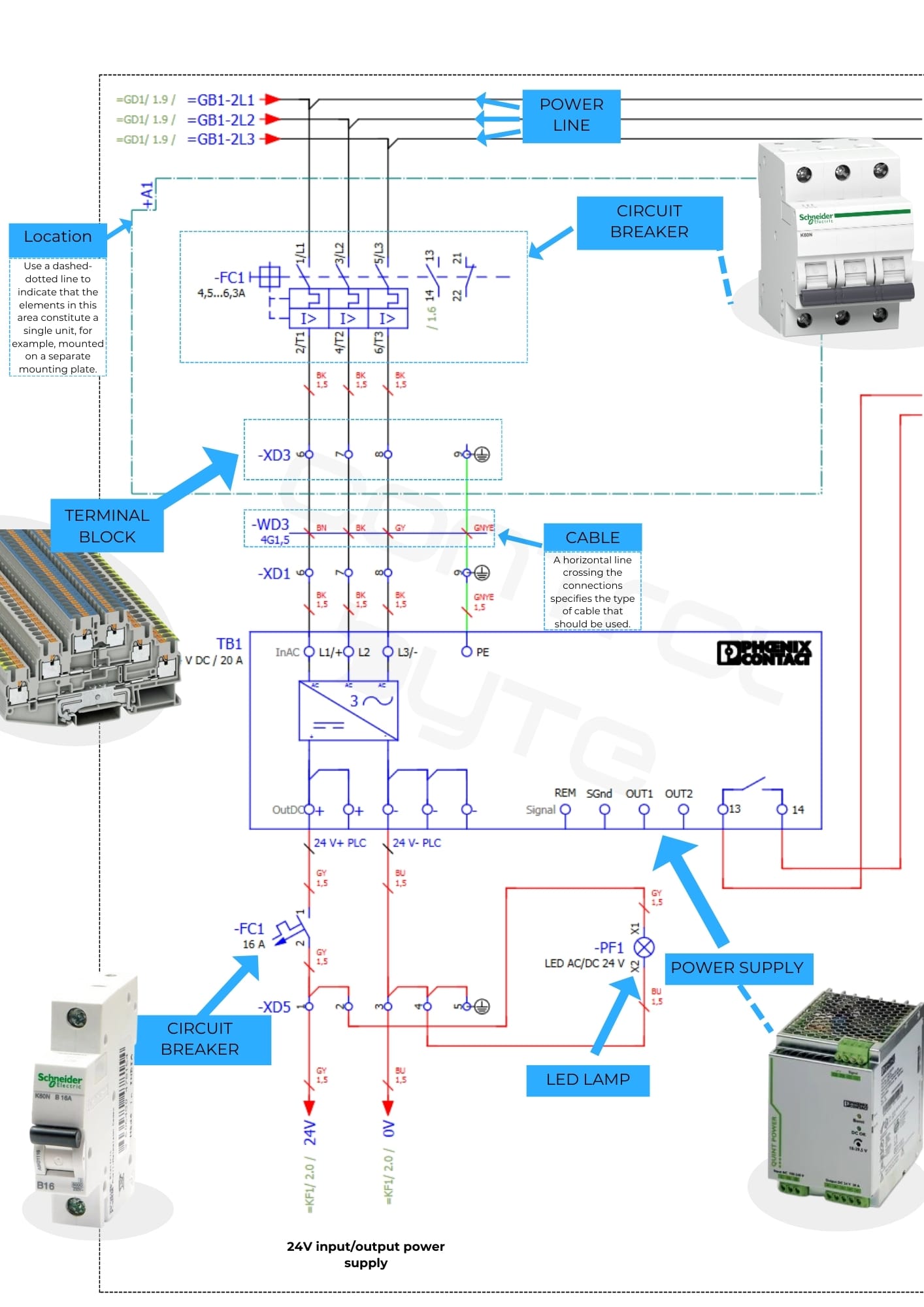
It is also helpful to work with the technical documentation of devices. Manufacturers often provide full electrical diagrams in user manuals. Analyzing these diagrams can help you learn to identify individual system components and understand their functions.
You can sign up for our Industrial Automation Basics and How to Read Electrical Diagrams Course, and we will send you a ready-made diagram to work on, after which you will design your own control cabinet.
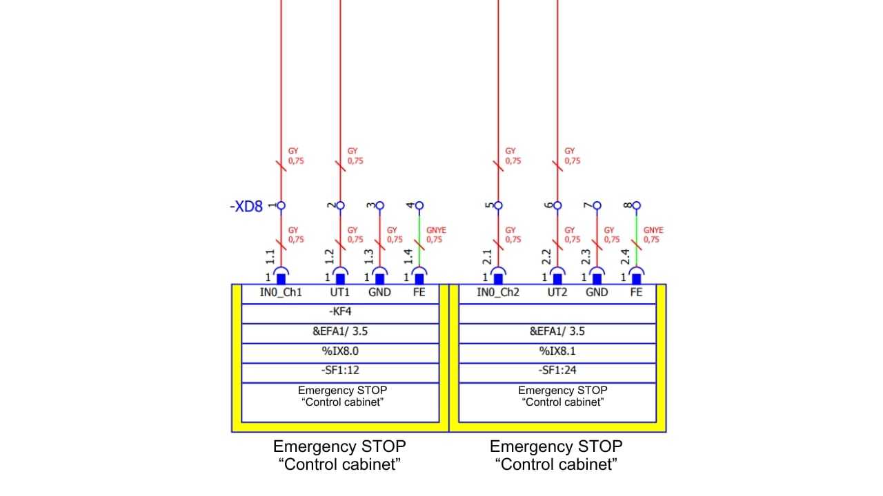
Additionally, in more complex systems, such as power systems in industrial production lines, diagrams include sections on protections, time relays, signaling, and emergency shutdown. Practicing with such diagrams will help you understand how complex systems work together and how important the proper connections and protections are.
Advanced diagrams
Electrical diagrams are becoming more complex in industrial applications, forcing designers to use various markings and structures to facilitate analysis and maintain order in the documentation. One important aspect is the identification of function, location, and product for each element in the diagram, according to standards like IEC 81346-1.
Using such markings significantly increases readability, especially when diagrams span dozens of pages and are part of larger systems with thousands of connections. This requires marking each element according to its function (equals sign), location (plus sign), and product type (minus sign).

- = FUNCTION – defines the function of an element, e.g., control circuits, 24VDC power supply
- + LOCATION – defines the location of the element, e.g., main switchboard +RG1, cross-connect cabinet +KS1
- – ELEMENT – target device, e.g., motor -M1, relay -K2
An example from actual documentation could show a control system for a production machine, where markings on different pages indicate specific workstations. For instance, if we are controlling a packaging machine, the function marking could show that the element is responsible for PLC power, the location indicates a specific place in the factory, and the product refers to a specific relay or motor in the system.
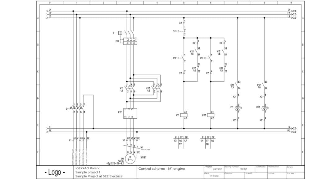
In advanced diagrams, such as transport systems or industrial production lines, the structure of diagrams is even more complex, as systems encompass many functions simultaneously. For each production station, it is necessary to design diagrams that allow precise tracking of all connections between automation, power, and protection elements. This helps avoid misunderstandings and errors during the operation or servicing of these complex systems.
Summary
Reading electrical diagrams is a fundamental skill for every electrician and automation technician. By correctly interpreting diagrams, you can diagnose faults, understand how installations work, and design new systems. The key to proficiency in this field is regular practice and understanding the basic symbols and connections.
Check out our courses related to electrical diagrams:
Familiarity with electrical diagrams is also invaluable when working with more advanced technologies, such as PLC controllers or industrial automation systems. As you gain experience, interpreting diagrams will become easier, and you will be able to analyze even the most complex systems with ease.

