Starting project template with PLC program and HMI visualization
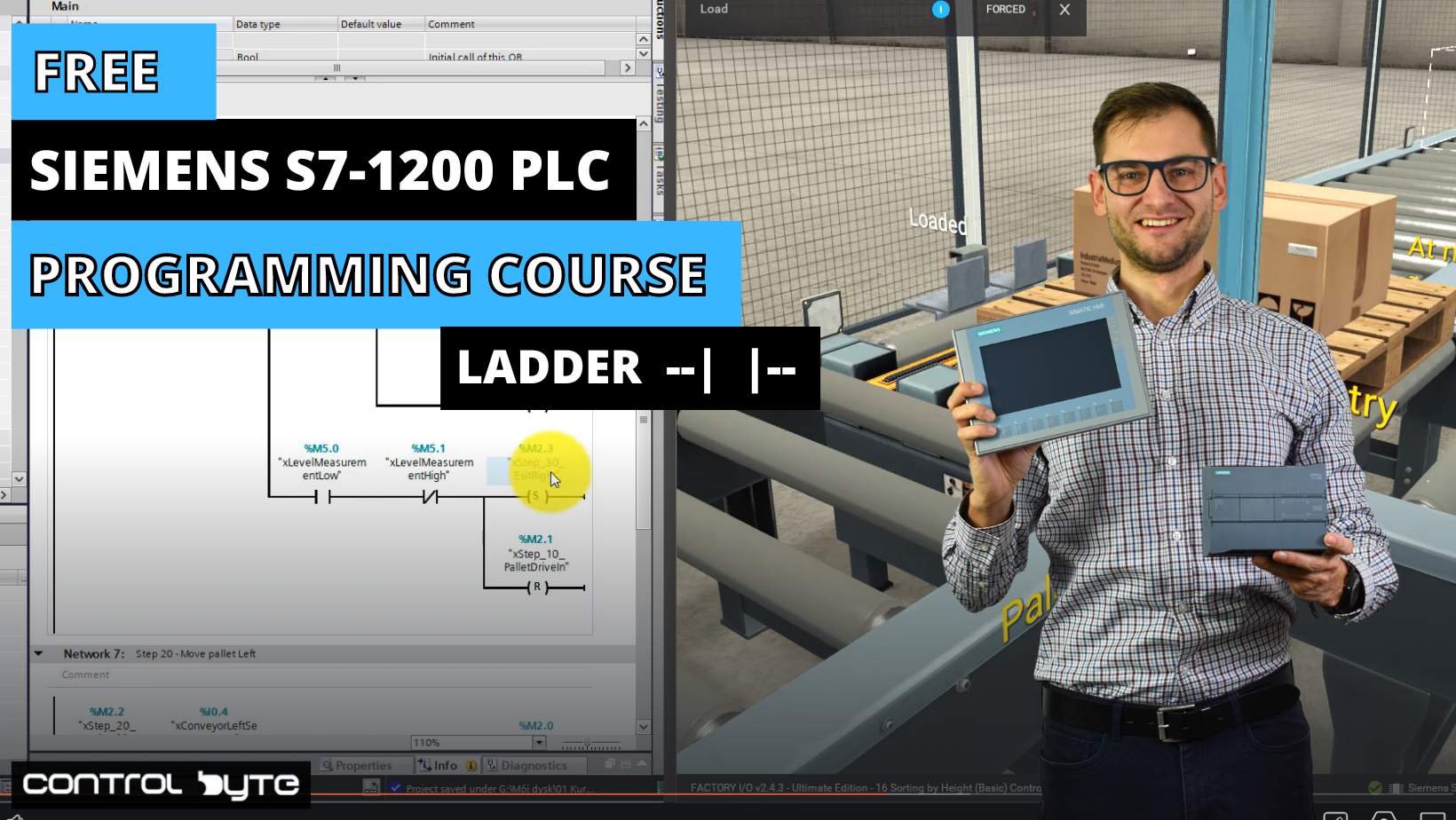
Download project template, follow the instruction and start PLCSIM and HMI simulation. With this template I will make an introduction into basic instructions of Ladder Logic – NO/NC contacts, AND, OR operations for Siemens PLC in TIA Portal.
Signals and variables in Siemens TIA Portal
In PLC programming for Siemens PLCs using TIA Portal, variables and constants are crucial for controlling and monitoring automation processes. First of all, a variable stores data that can change during program execution, such as sensor readings or motor speeds. On the other hand, constants hold fixed values, like setpoints or configuration parameters, that remain unchanged throughout the program.
Each variable or constant in TIA Portal has a specific address in CPU memory, which the PLC uses to access or modify the data. Additionally, variables come in various data types, such as Bool, Byte, Word, Integer, or Real. Depending on the kind of information they store, you will use different variable types. TIA Portal’s interface makes it easy to create and manage these variables. Furthermore, you will find options for naming, setting data types, defining memory addresses, and adding comments for clarity.
For example, in an industrial automation system, you might use a Boolean variable to monitor a conveyor belt’s status (on or off). At the same time, a constant can define the belt’s maximum speed. The Boolean variable can change during the program based on sensor inputs, while the constant value remains fixed.
Ladder logic introduction in Siemens TIA Portal
In TIA Portal, ladder logic serves as a graphical programming language for designing PLC programs. Ladder logic closely resembles electrical relay logic diagrams. The ladder diagram contains networks that function as separate code blocks. Inside each network, users create rungs to represent the control flow from left to right. These rungs include input elements like Normally Open (NO) or Normally Closed (NC) contacts, which simulate sensor inputs or operator actions. At the end of each rung, a coil activates devices such as motors, valves, or lights.
The code editor in TIA Portal provides an organized interface for easily creating, editing, and managing networks and rungs. For example, a NO contact labeled “Start” can initiate an action, and the coil at the end of the rung will control an output, such as extending a cylinder. Each rung element connects directly to specific memory addresses or tags, allowing for seamless integration with physical inputs and outputs. Understanding this process is crucial for anyone looking to master PLC programming in TIA Portal.
Basic boolean operations in Ladder Logic
In ladder logic programming within TIA Portal, Boolean logic is fundamental to controlling automation processes. Boolean operations are based on two states: True (1) and False (0). They govern how inputs are evaluated to produce an output. Common Boolean operations include AND, OR, and NOT, which you can implement using basic elements such as contacts and coils in ladder logic.
For example, two Normally Open (NO) contacts, labeled as “%I0.0 Start” and “%I0.2 SelectExt_T”, are placed in series within the same rung. This represents an AND operation. It means that both conditions must be true for the connected output, represented by the coil “%Q0.3 Extend_Y2”, to be energized. In contrast, if these contacts were arranged in parallel, it would represent an OR operation. OR operation means that either condition could trigger the output.
Boolean logic is key to creating conditions for activating or deactivating outputs, controlling machinery, or managing sequences in industrial automation. Understanding how to implement Boolean logic in ladder logic helps programmers efficiently build decision-making routines.


Very insightful.