Overview of the Siemens Simatic S7-1200 Compact – Basic Operating Modes
Hello, esteemed readers. In this post, I will cover the basics of how the Siemens S7-1200 PLC controller operates. I’ll describe its operating modes and types of program blocks. This knowledge is essential for effectively programming this PLC model.
PLC Operating States and Functionality
The S7-1200 controller has three operating modes:
- STOP
- START UP
- RUN
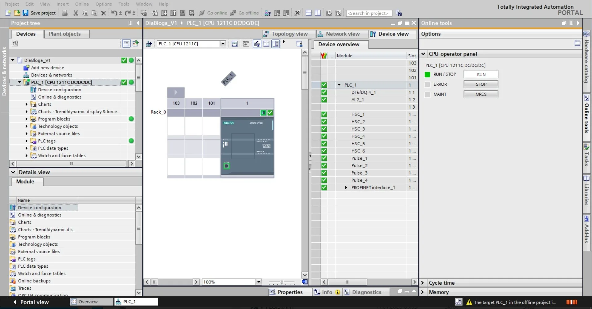
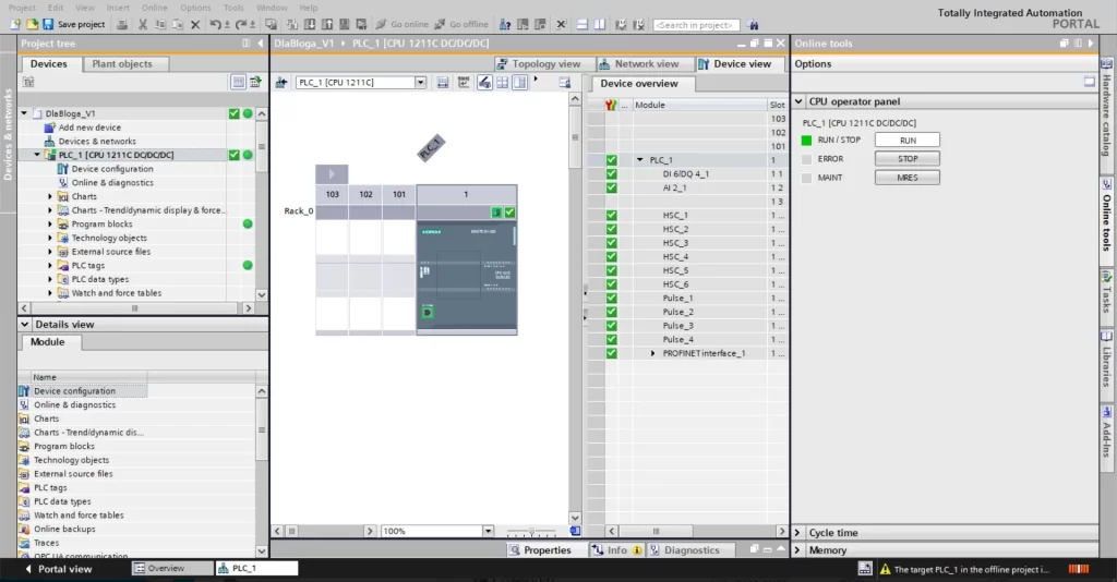
These controllers do not have any physical switch or button to change modes. To switch modes, you need to use the appropriate option in TIA Portal.
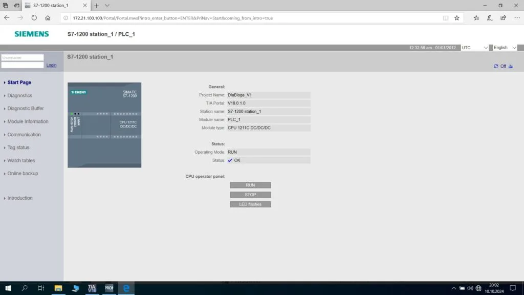
You can also activate the web server on the controller, allowing you to change the mode.
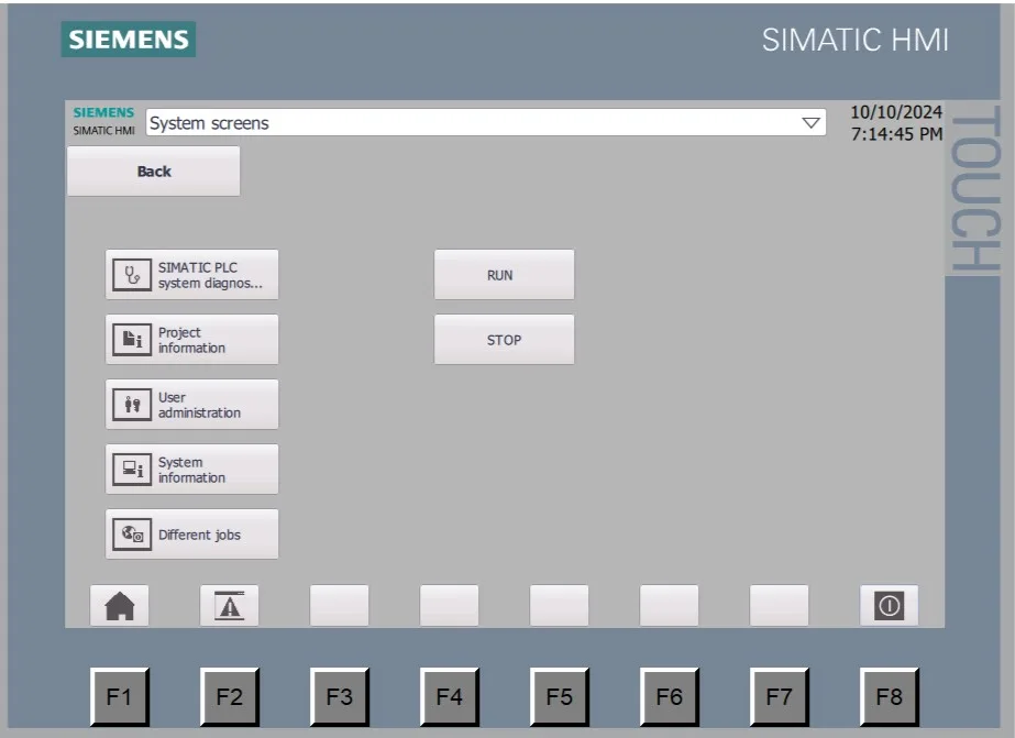
Alternatively, if you have access to a Siemens HMI panel, you can program it accordingly and use it to change the mode.
STOP Mode
In this mode, the controller does not execute the user program and, most importantly, does not activate outputs; it sets all outputs to a low state. Therefore, in most cases, this creates a safe state for the machine or installation controlled by the PLC. The controller may automatically switch to STOP mode when it encounters a failure, such as signal module damage, module replacement, or power issues.
You need to set the controller to STOP mode when uploading hardware configurations or making significant program changes, such as reinitializing and uploading data blocks.
Thus, when working on active installations, exercise extra caution, as an uncontrolled shutdown of certain machines or installations could cause significant losses or even catastrophic risks.
The controller signals this mode with a continuous orange light on the RUN/STOP LED on its front panel.
START UP Mode – Initializing System Operations
This is a transitional mode between STOP and RUN.

It consists of six steps, the successful execution of which leads from STOP to RUN mode. These steps are:
- Clearing the input image memory of PIPI.
- Initializing the output image with zeros, the last value, or a preset value.
- Initializing variables to start values, enabling interrupts, executing startup OBs.
- Updating the input image of PIPI.
- Queuing interrupts for execution in RUN mode.
- Allowing the output image to be written to the controller’s physical outputs.

RUN Mode
This mode is indicated by a blinking green light on the RUN/STOP LED on the front of the controller.
In this mode, the controller continuously executes the user program, thus ensuring the operation of the machine or installation. This cycle consists of four steps executed in an infinite loop:
- Copying the processed output state from the controller’s PIPQ output memory area to its physical outputs.
- Checking the state of the physical inputs and saving it to the controller’s PIPI input memory area.
- Executing the user program.
- Performing self-diagnostics.
- Additionally, communication is handled in parallel to the program cycle, and an interrupt can be triggered and handled at any moment.
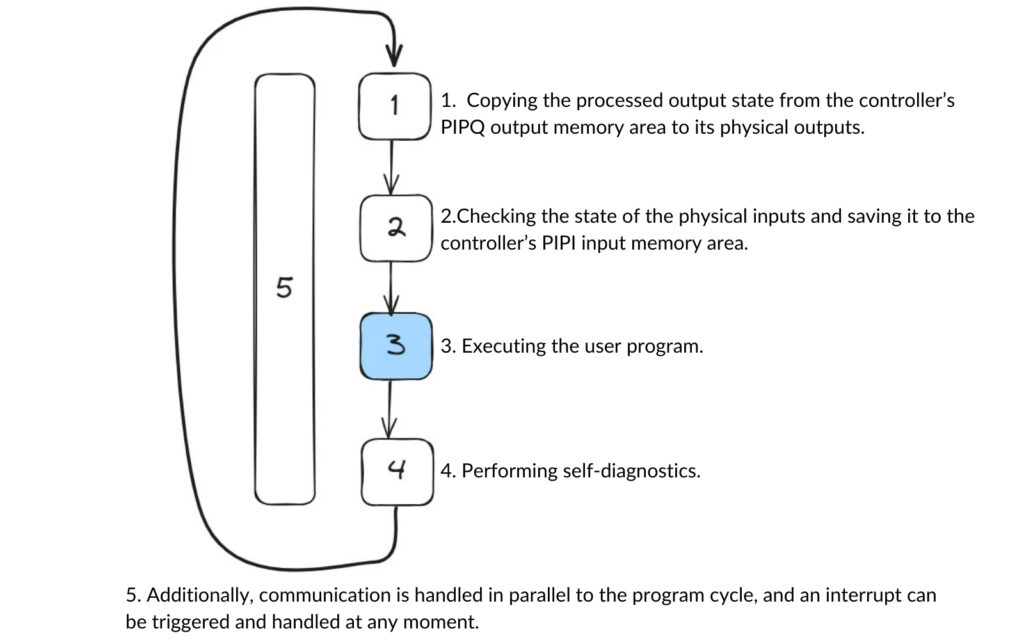
Operating Cycle in RUN Mode
This mode is indicated by a continuous green light on the RUN/STOP LED on the front of the controller.
Basic Types of Program Blocks
The S7-1200 controllers have four types of program blocks:
- OB – Organizational Block: These blocks are triggered by the controller upon specific conditions and are used to organize the user program and control the controller’s operation.
- FC – Function: Similar to functions in other programming languages, these blocks contain parts of the program that perform specific tasks often repeated in a project, such as valve control.
- FB – Function Block: A function block with associated memory, allowing for more advanced control logic. An FB must be paired with a Data Block (DB) that acts as its memory. FBs can control specific segments of a production line, such as elevators or conveyor tables.
- DB – Data Block: Memory areas where the programmer defines custom variables globally available to all program blocks. They can also serve as memory areas for FBs, then known as instance DBs paired with Function Blocks.
Organizational Blocks (OB) – Structuring Control Logic
These blocks control the invocation of the user program, creating a certain structure within it. They cannot be called by other blocks; instead, the PLC triggers them based on specific events, invoking the appropriate OB. Some blocks have predefined actions and entry points, while others allow more configuration flexibility. Below, I’ll describe the most important OBs:
- Cyclic OB (Program cycle): Contains the main user program, typically numbered OB1. In RUN mode, once completed, the CPU immediately re-triggers and re-executes it. This block has the lowest priority (1), meaning any other block will interrupt its execution. Multiple cyclic blocks can be present, triggered in sequence by their numbers, with the last one leading back to the first.
- Startup OB: Executed once in START UP mode just before the Cyclic OB. The controller usually assigns this block the number OB100, and it contains instructions that execute once at machine startup, such as resetting counters, parameterizing functions, overwriting parameters, or initializing peripherals. Multiple startup OBs can exist, and the controller calls them in numerical order.
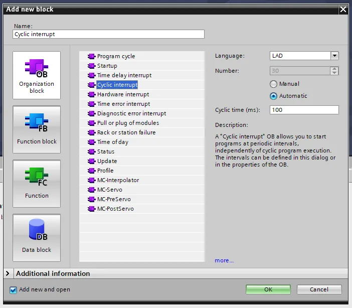
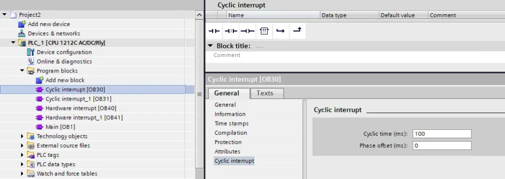
- Cyclic Interrupt: Triggered at user-defined intervals (e.g., 100ms), interrupting the Cyclic OB to execute its instructions. Typically numbered from OB30 to OB38 or above OB200. Up to four such blocks can run simultaneously on one CPU.
Using more than one cyclic interrupt allows time-shift settings to avoid overlap, ensuring that high-priority blocks do not wait for lower-priority ones. For example, if a 100ms block overlaps a 1000ms block every tenth cycle, setting a 30ms delay for the 1000ms block prevents overlap.
Hardware Interrupt:
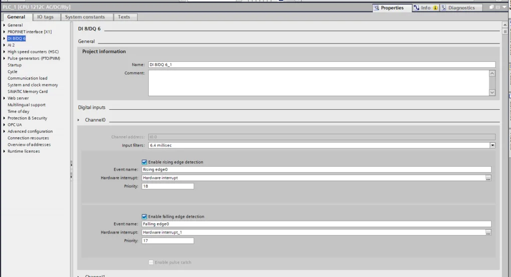
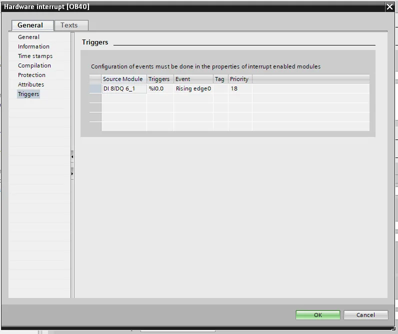
Triggered by significant hardware events, such as a signal edge on built-in digital inputs. Defined in hardware configuration, events determine which hardware interrupt block (OB40, etc.) is invoked. Up to 50 hardware interrupt blocks can exist, typically numbered OB40 to OB47 or above OB200. These interrupts have a higher priority than cyclic interrupts and Cyclic OB, ensuring immediate execution. These blocks are best for handling fast-changing signals, like encoder readings.
Time Error Interrupt:
If the defined cycle time is exceeded in the hardware configuration, it defaults to putting the CPU in STOP mode. However, adding this block (OB80) lets you execute additional code to decide whether to stop or continue the CPU. Only one OB80 block can exist per project, with the highest priority (26).
Diagnostic Error Interrupt: Triggered when a module reports a diagnostic error, with only one such block (OB82) allowed per project.
Function (FC) – Defining Specific Operations
This block type, essentially a subroutine, performs specific operations on input values and outputs results. FCs do not retain memory; temporary data within the block is stored on a local data stack and discarded after execution. These blocks are ideal for:
- Standard and repetitive operations, like arithmetic calculations.
- Functional tasks, such as individual control using logic operations.
Function Block – FB
This block type functions like a subroutine with memory, retaining input, output, in-out, and static variables in an associated DB or instance DB. This memory persists across cycles, making FBs suitable for continuous control tasks. A conveyor control example could involve sensors for item detection and relays to activate motors. A bit of memory would indicate the item’s position, reset only after it exits the conveyor, allowing for a new item to enter.
FBs can be associated with multiple DBs, allowing the same FB to control different devices with unique parameters stored in each DB.
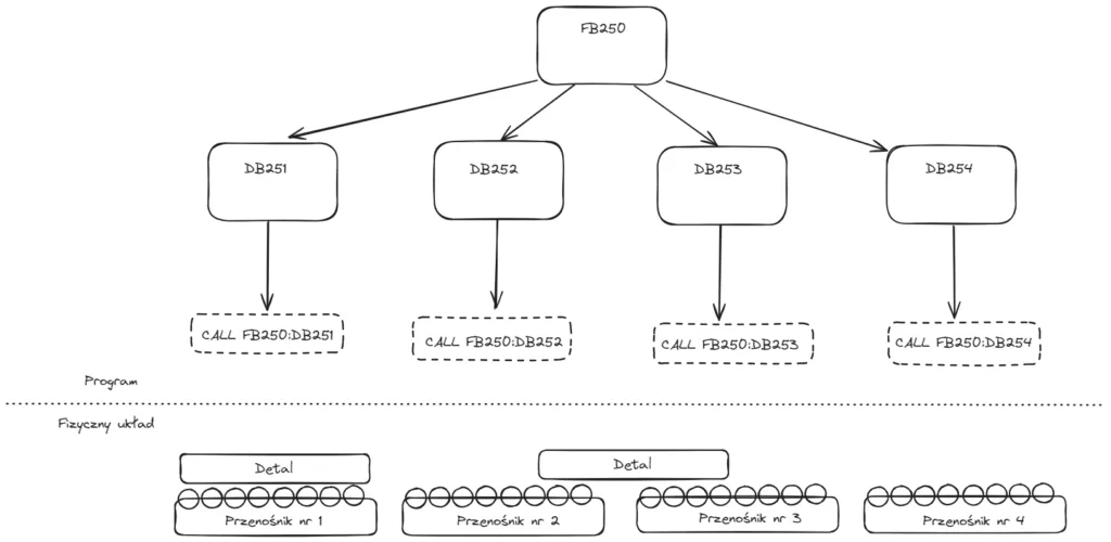
Data Block (DB) – Storing Key Variables
DBs are used in user projects to store data for code blocks. There are two types:
- Global DB: Holds data accessible to any OB, FB, or FC and can be set to read-only.
- Instance DB: Stores data for a specific FB, mirroring the FB’s input, output, in-out, and static parameters. Temp memory in FB is not retained in instance DB, but all blocks in the project can access the instance DB contents.
This concludes the overview of the S7-1200’s operation. For those interested, I’ll leave links to the manufacturer’s documentation with further details on this family of controllers.
Thank you for reading! If you’re interested in learning more, explore our courses for in-depth training: Control Byte Courses.
Conclusion – Comprehensive Guide on Siemens S7-1200
If you’re starting your journey with Siemens SIMATIC S7-1200, this guide gives you a clear understanding of how the controller works in STOP, START UP, and RUN modes. You’ve learned how these states affect program execution.
We also explored the main program block types — OB, FC, FB, and DB — and how to use them to create structured, modular, and reliable automation programs. With examples of cyclic and hardware interrupts, you now know how to make your logic react instantly to real-world signals.
Continue your learning journey and practice these concepts in real projects through ControlByte’s PLC training courses.

