The Finder Opta programmable relay, with its unique design, enables precise control over various production processes. It plays a crucial role in modern industrial automation. This advanced solution combines functionality, reliability, and flexibility. These qualities make it ideal for a wide range of applications, from simple tasks to complex control systems. This article covers the capabilities and benefits of the OPTA controller, explains its popularity across industries, and shows how its innovative features improve process optimization and operational efficiency.
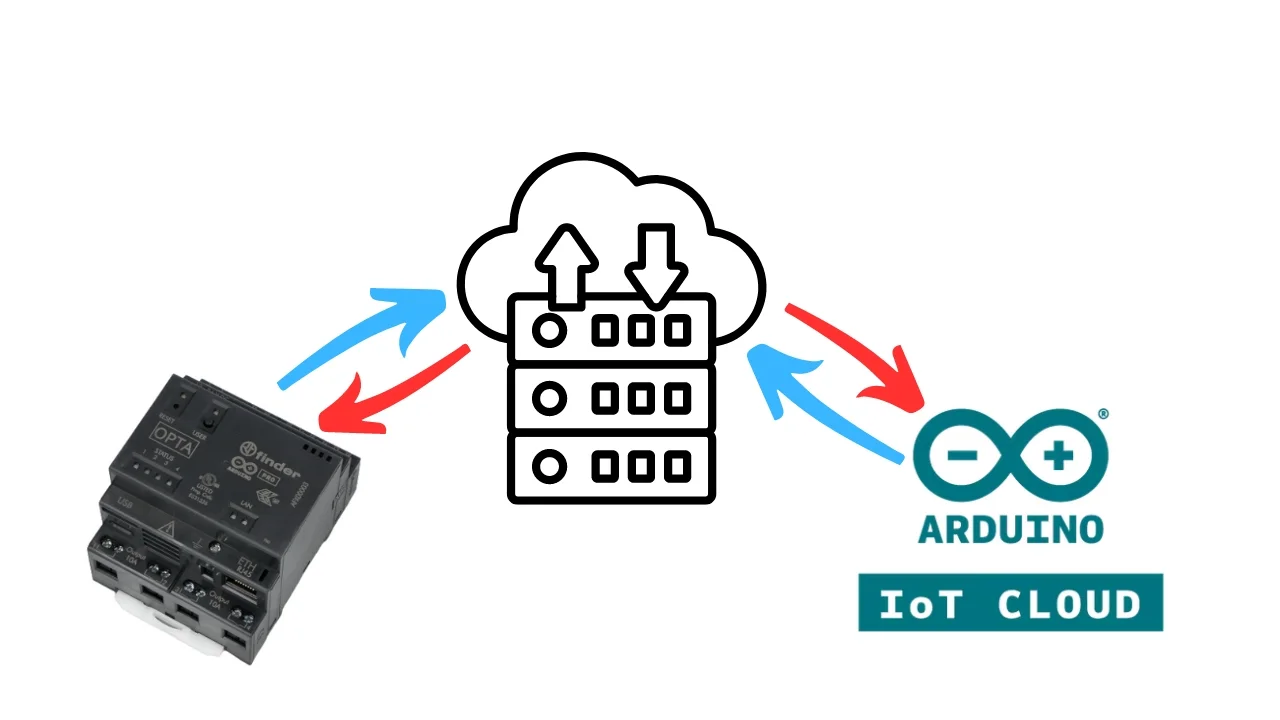
Arduino Cloud and Over-The-Air (OTA) Programming of the Finder Opta Programmable Logic Relay
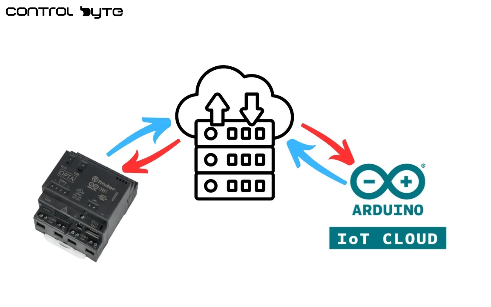
As is well known, three versions of this device are available on the market: LITE, PLUS, and ADVANCED—all powered by 12-24VDC, yet differing in their interfaces. The highest version, Advanced, garners the most interest due to its ability to fully leverage the controller’s potential. It supports protocols like ModbusTCP and ModbusRTU and enables communication via WiFi and Bluetooth. The WiFi protocol greatly facilitates code updates through remote OTA updates and allows cloud connection for remote monitoring and control of production processes. Programming can be done in selected IEC 61131-3 PLC languages, such as FBD or ST.
How is the Cloud and remote update configured?
If an icon like the one in the image below appears in your cloud project, it means the Finder Opta in the project is powered by 12-24V DC, connected to WiFi, and communicating with the cloud. When the arrow icon is green, pressing it allows you to start uploading the program to the controller.

After pressing the arrow, the console shows that the Over-The-Air procedure is available, and its initialization begins.

Next, a request to upload the written code is created.

Finally, we see that the update has been successful, and our device has been correctly reprogrammed.

This procedure is possible after adding the controller to Arduino Cloud and completing initial setup via a USB-C cable. This feature simplifies upgrades to existing installations, avoiding costly service trips to distant production facilities. It reduces travel costs and time, but most importantly, it minimizes production downtime.
Overview of the Cloud Homepage Interface
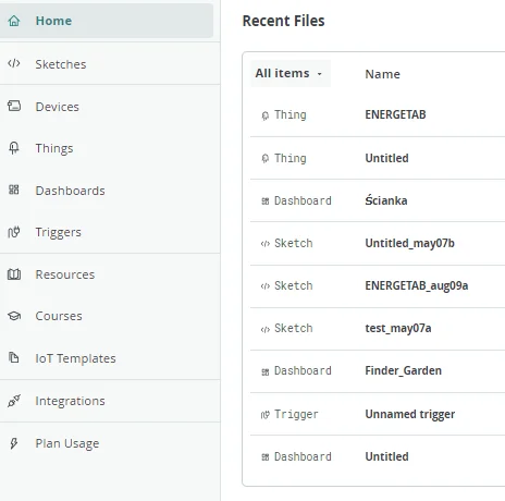
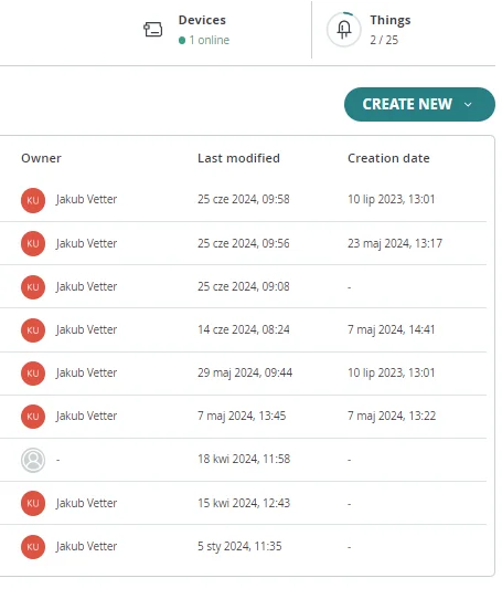
On the cloud’s homepage, the left side displays functions like added devices, visualizations, and ‘Things’ for creating variables from values collected via Finder Opta. The right side lists recently used and updated functions, with names, modification dates, and creation dates in chronological order. The interface shows who created each project when shared by another user. At the top, you’ll find a button for creating new functions, along with indicators for the number of devices connected to the cloud and how many additional ‘Things’ can still be created.
Creating New Variables and Configuring Finder Opta
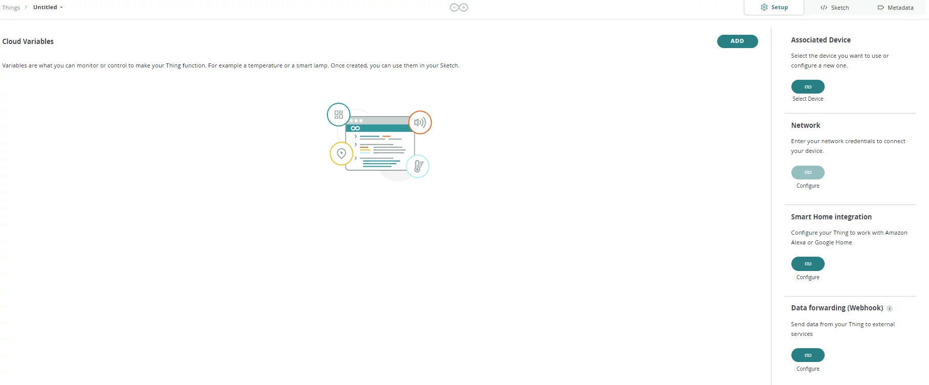
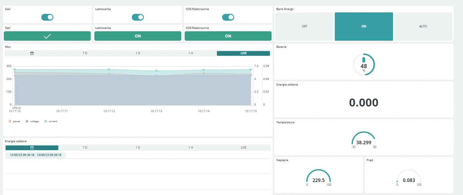
Clicking ‘Create New’ and selecting ‘Things’ opens a window to create variables, assign devices, configure WiFi or Ethernet, and integrate with smart home systems or other services. You can also access the Sketch tab here to develop your program, with the variables automatically initialized in the code.
Ensuring System Reliability with Alarms and Interrupts
Alarms and interrupts are essential for ensuring reliability and precision in control systems. These features enable systems to respond immediately to unforeseen events, reducing failure risks and optimizing production. Interrupts allow quick responses to external or internal events without constant signal monitoring. They pause normal execution to let the controller handle tasks like button presses, data reception, or error management.
The following describes a program in Arduino IDE that uses interrupts to manage button state changes and simulate voltage levels. This program can also be developed in a PLC IDE. Its main goal is voltage monitoring: when voltage is 24V or below, the program activates the LED and relay to signal a normal state. If voltage exceeds 24V, the LED signals an error, and an interrupt pauses operations to handle the fault.
Defining Variables and Initial Setup
Initially, we define the variables to be used in the program. The variable errorVoltage holds the constant voltage value that signals an error. Voltage stores the current voltage. Relay is set to pin D0, which is the Finder Opta relay output, potentially connected to an external device, while led1 and led4 are internal LEDs on the Opta that indicate interrupt activity. ButtonPressed is a flag variable set to true within the interrupt service function, signaling that the button has been pressed. The status variable is a boolean that holds the button’s state, initially set to false.

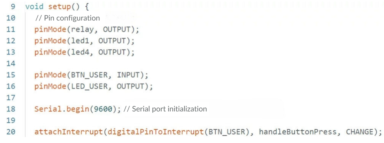
The output pins for the relay and LEDs are then set up. Additionally, the user button pin, BTN_USER, is configured as an input, while the LED_USER pin, used to visualize the button’s status, is set as an output. The Serial.begin() function initializes serial communication at 9600 bps for monitoring the status. Meanwhile, the attachInterrupt function configures an interrupt on the BTN_USER button for a state change (CHANGE), meaning the interrupt will trigger each time the button is pressed or released.
Main Program Loop Functionality
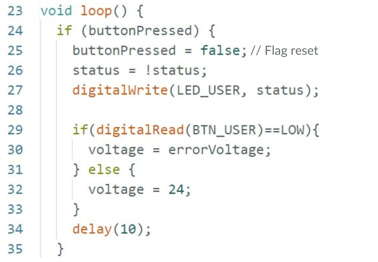
The loop() function is the main function of the program and includes two if statements. In the first if condition, the buttonPressed flag is checked. When the flag is set to true, it indicates that an interrupt has been triggered. The flag is then reset to false. The status variable is toggled (reversed), which updates the state of LED_USER, indicating a button press. The digitalRead(BTN_USER) function checks whether the button is currently pressed. If it is, the voltage value is set to errorVoltage. Otherwise, the voltage is set to the standard value of 24V. A short delay is added to prevent rapid state changes.
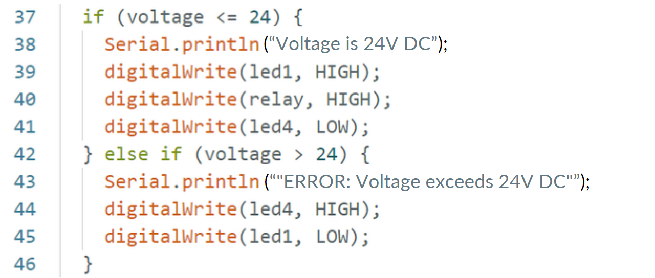
In the second if condition, based on the voltage value, appropriate messages are sent to the serial port, and the LEDs are turned on or off. If the voltage is valid (i.e., less than or equal to 24V), led1 and the relay output are activated. However, if the voltage exceeds 24V, led4 indicates an error, and an error message is sent, signaling that an interrupt has been triggered.
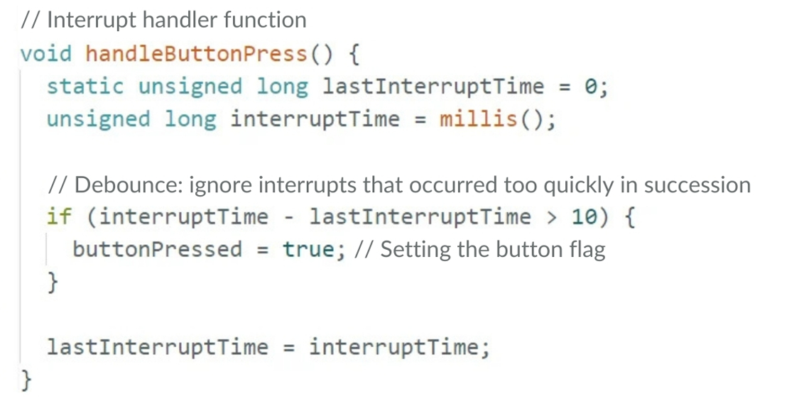
The handleButtonPress() function is responsible for handling the interrupt associated with pressing the button. The variable lastInterruptTime stores the time of the last interrupt occurrence to prevent multiple button bounces (debouncing). Inside the function, the code obtains the current time using the millis() function and stores it in interruptTime. The condition if (interruptTime – lastInterruptTime > 10) checks if the time since the last interrupt is greater than 10 milliseconds, indicating a stable button press. If the condition is met, the code sets the buttonPressed flag to true, signaling the main program loop that an interrupt has occurred. Finally, it updates lastInterruptTime with the interruptTime value to prepare for the next interrupt. This function ensures reliable button handling by eliminating accidental signal bounces.
Data Logging and Modbus RS-485 Communication – Enhanced Flexibility
In the era of Industry 4.0 and increasing automation, data collection and analysis are essential for effective industrial process management. Programmable controllers, central to modern automation, not only control machines but also gather extensive operational data. Analyzing this data provides insight into performance, identifies issues, and optimizes efficiency. Finder Opta, for instance, collects data from devices like energy meters and saves it to a file for later verification and comparison in advanced programs.
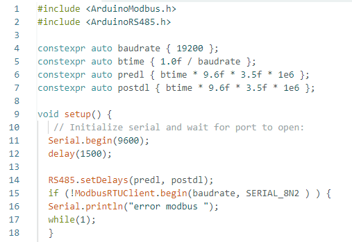
The code begins with necessary libraries for RS-485 communication and configuration parameters. These settings, applied during Opta’s initialization, ensure stable RS-485 data transmission by defining communication timing. Matching transmission speeds between devices is crucial for reliable operation.
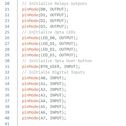
The next step is to initialize all used inputs, outputs, and LED indicators.
Reading and Converting Data from the Energy Meter
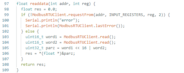
Next, extend the program with a function to read data from the energy meter using the appropriate registers. Per ModbusRTU instructions for the Finder 7M energy meter, each parameter, like voltage or current, requires two registers for reading. The meter reads an analog value. In the reading function, we first check whether RS485 communication is established. If not, the code flags a communication error; if successful, it reads the first register (word1), then the second (word2), and merges them with a bitwise shift. The next step is to convert the read values to the correct units.
The next step is to assign the read values of power, voltage, and current to the appropriate variables in the main program execution function and then display them in the Serial Monitor window.
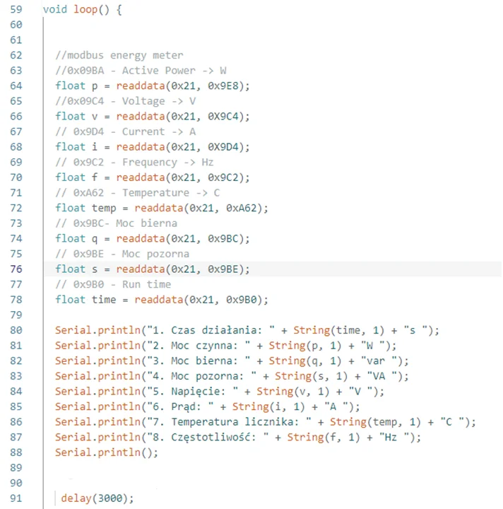
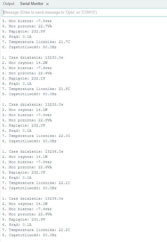
In this example, all read values are displayed with a 3-second interval. However, both the interval and the display format can be customized according to user needs. The values below are a sample of those available in the energy meter. All readable values are listed in the 7M meter’s Modbus protocol manual.
Saving Data with CoolTerm
To save the displayed data, you can use the free software CoolTerm and set the appropriate communication parameters to match those in the Arduino IDE.
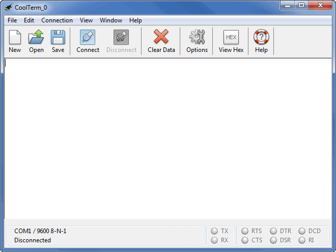
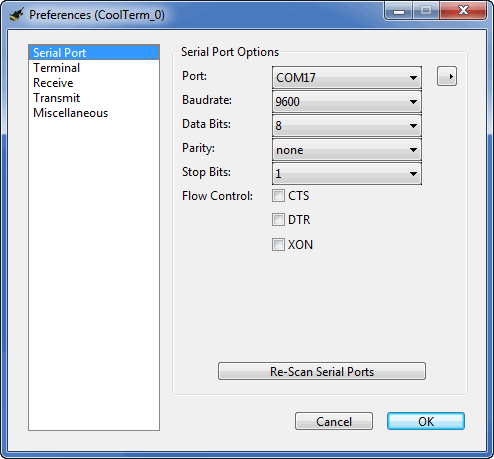
In the final step, go to Options > File Capture. Enable ‘Add timestamps’ to include dates in readings, ‘Autostart on open’ to save data automatically, and choose the file location for captured data.
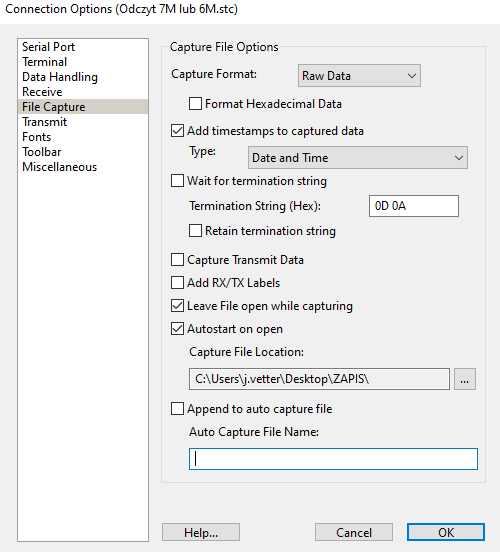
After configuration, the program receives data from the Serial Monitor and saves it to a .txt file in the chosen location. You can also set it to record the date and time of each reading for more precise analysis
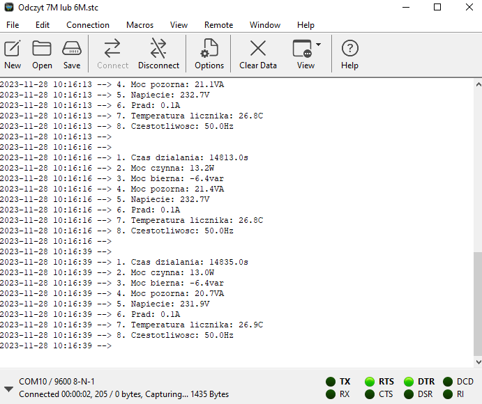
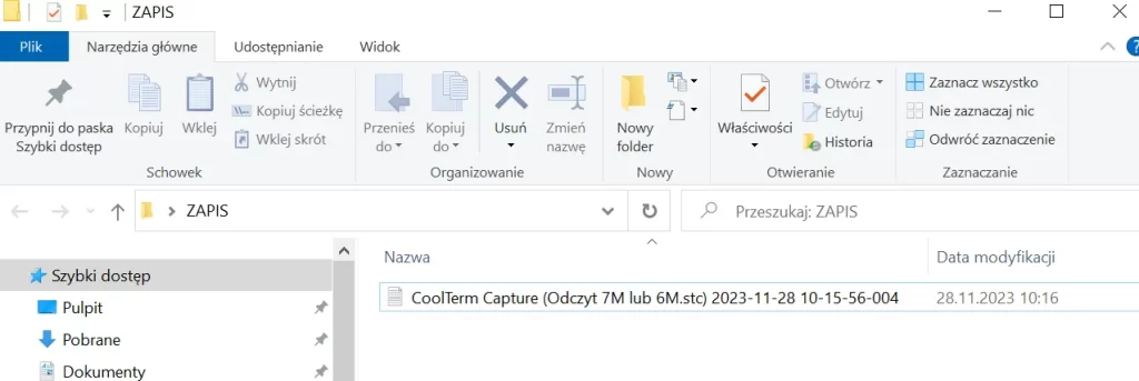
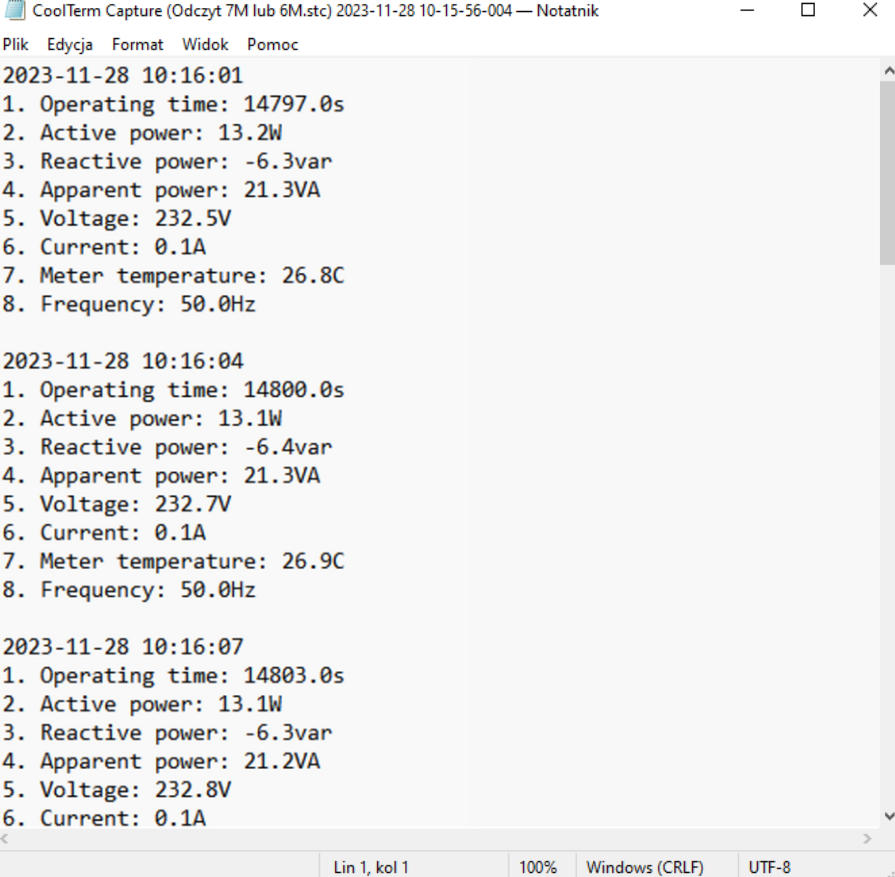
As shown, the solution offered by Finder has immense potential. The controller manages home and industrial automation and excels in in-depth analysis of machine operations and industrial processes.
Choosing the OPTA programmable relay provides access to free software and a large library of solutions and ready-made code from Arduino users. For more information, visit Finder’s website: https://opta.findernet.com/

