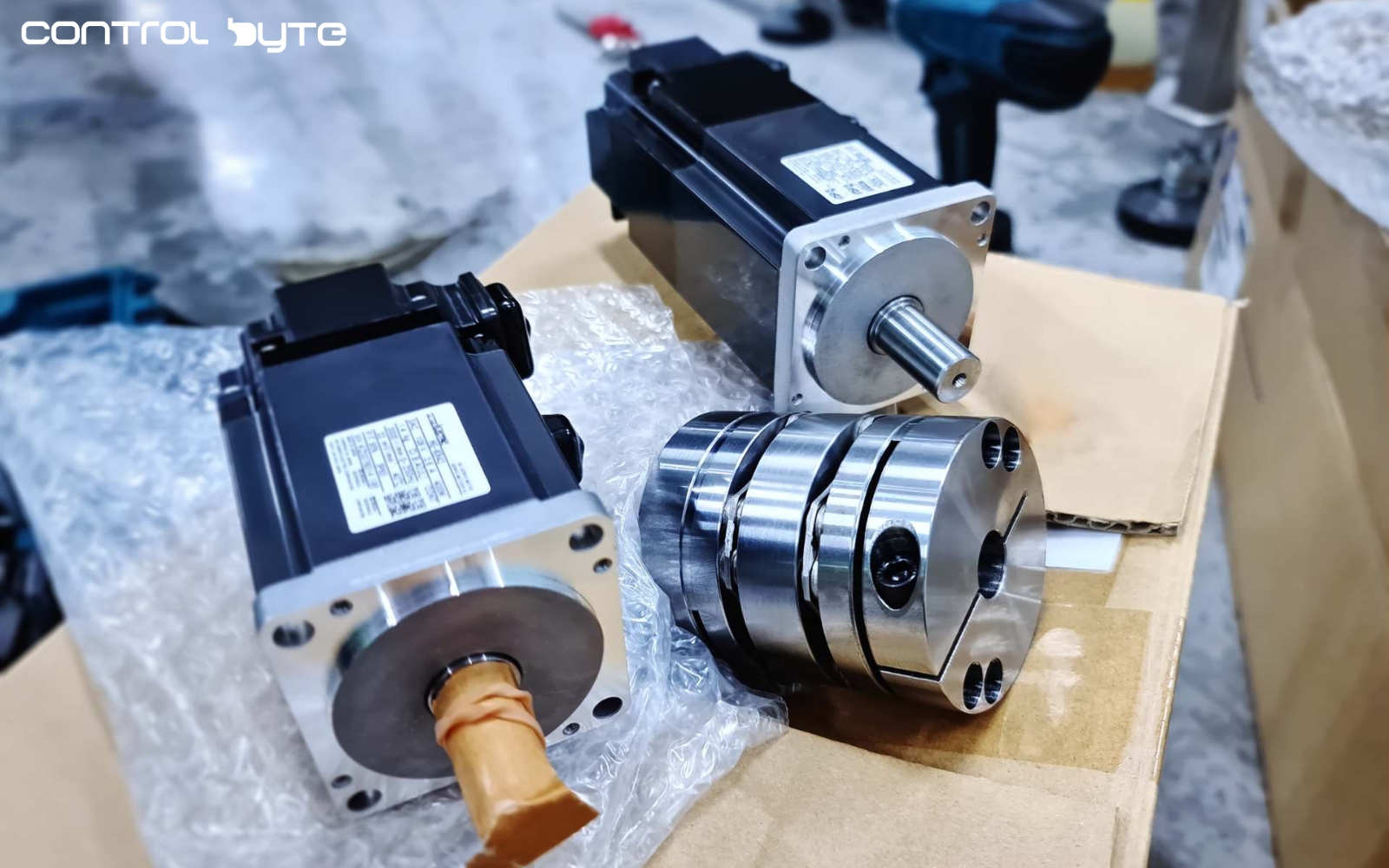
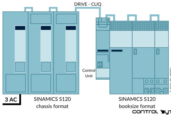
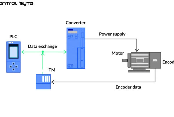
Since 2019, we have been conducting PLC programming courses. Over this time, hundreds of people have completed our online PLC programming training.
We’ve often been asked:
“When are new courses coming? Are you planning to offer a course on drive programming?”
Creating an online course for programming industrial automation devices is no easy task! It requires a lot of time… The materials and exercises need to be adapted to the e-learning format. All the exercises included in the course can be performed on your computer, based on a digital twin of a real setup with equipment.
This training format is a novelty on the market! It has allowed us to build a large community of automation professionals on our platform.
For several months, we’ve been working on a servo drive programming course using our proven online training format, featuring a simulation setup—a digital twin.
In this article, I want to show you the tools available on the market that will enable you to master drive application creation based on global standards within three weeks.
1. Learning Siemens Drive Programming
Siemens PLCs and drives are the standard in today’s automation world. In the European market, this equipment represents about 40-50% of the devices used in industry.
When I started my journey with PLCs (back in 2010), only basic simulators for PLCs were available. Drive simulation was something we could only dream about.
With the introduction of TIA (Totally Integrated Automation) Portal and the PLCSIM simulator available within it, the possibilities for testing automation applications began to expand.
A breakthrough came with the introduction of an advanced version of the simulator—PLCSIM Advanced (currently version 4.0). Using SIMATIC S7-PLCSIM Advanced, you can create virtual instances of controllers to simulate CPU S7-1500 and ET 200SP. The S7-PLCSIM Advanced simulator enables the simulation of blocks related to technology objects and motion control.
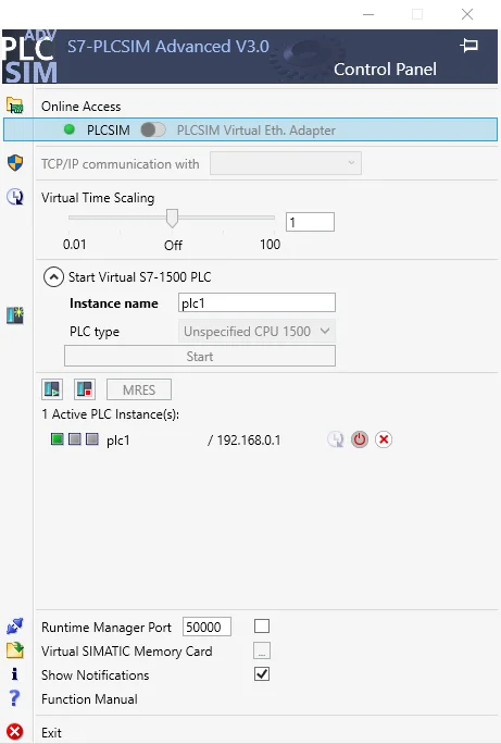
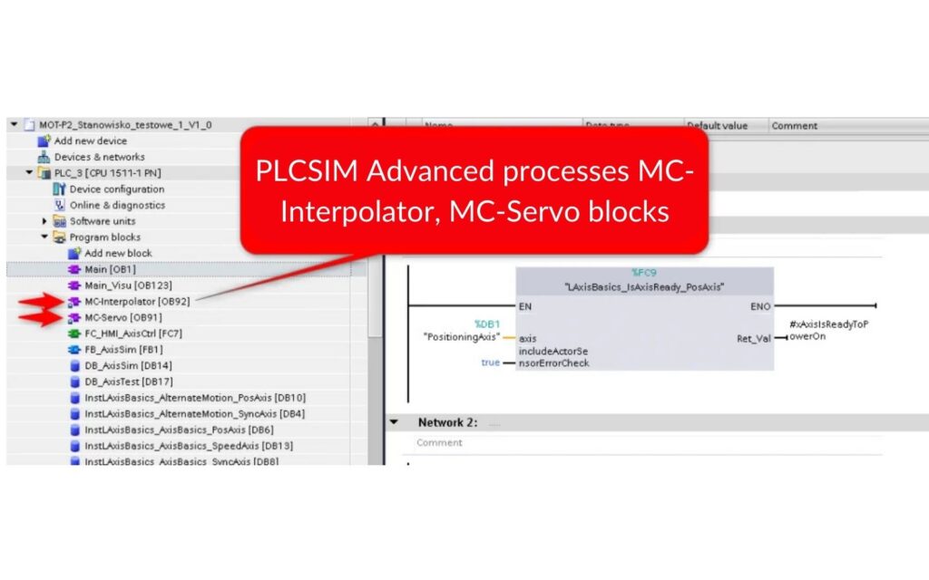
When creating a drive application project in a PLC, blocks like MC-Interpolator, MC-Servo (as well as MC-PreServo and MC-PostServo) are generated automatically. The standard PLCSIM simulator lacks the functionality needed to test such an application. For this task, PLCSIM Advanced is essential.
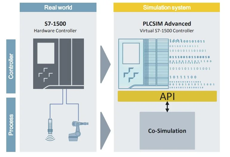
The PLCSIM Advanced simulator allows connection, via API, to any automation simulation environment. This could be Factory IO, Siemens NX, or SIMIT + Unity. You can independently create a simulation system for your setup in any system and integrate it via API.
2. Program a Flying Saw on a Siemens PLC and Test on Your PC
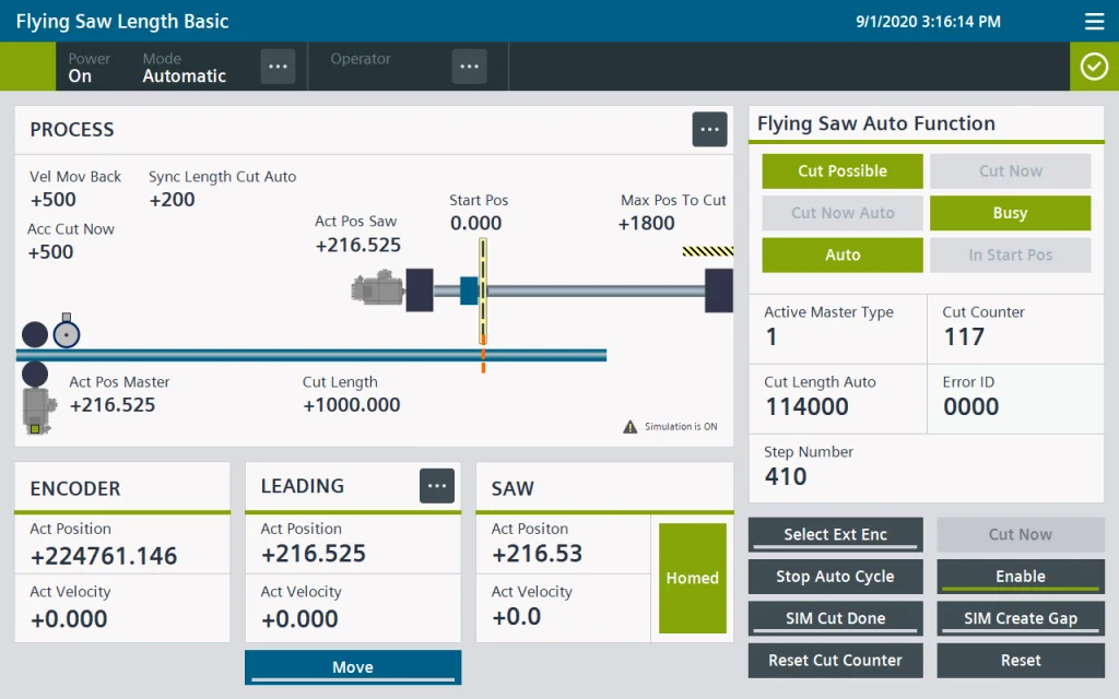
A standard drive application that uses more advanced functions, such as axis synchronization, is the so-called Flying Saw. In this process, the material moves continuously (e.g., foil, metal, paper, corrugated cardboard, steel profiles, etc.). The saw carriage synchronizes its speed with the material feeder, performs the cut, and returns to its starting position. After detecting the next marker or reaching a set length, the cycle repeats.
You can easily test such an application using the PLCSIM Advanced simulator! There are also sample 3D models created in Unity. By linking the PLC simulator with 3D visualization through SIMIT software, you can fine-tune your drive application down to the smallest details.
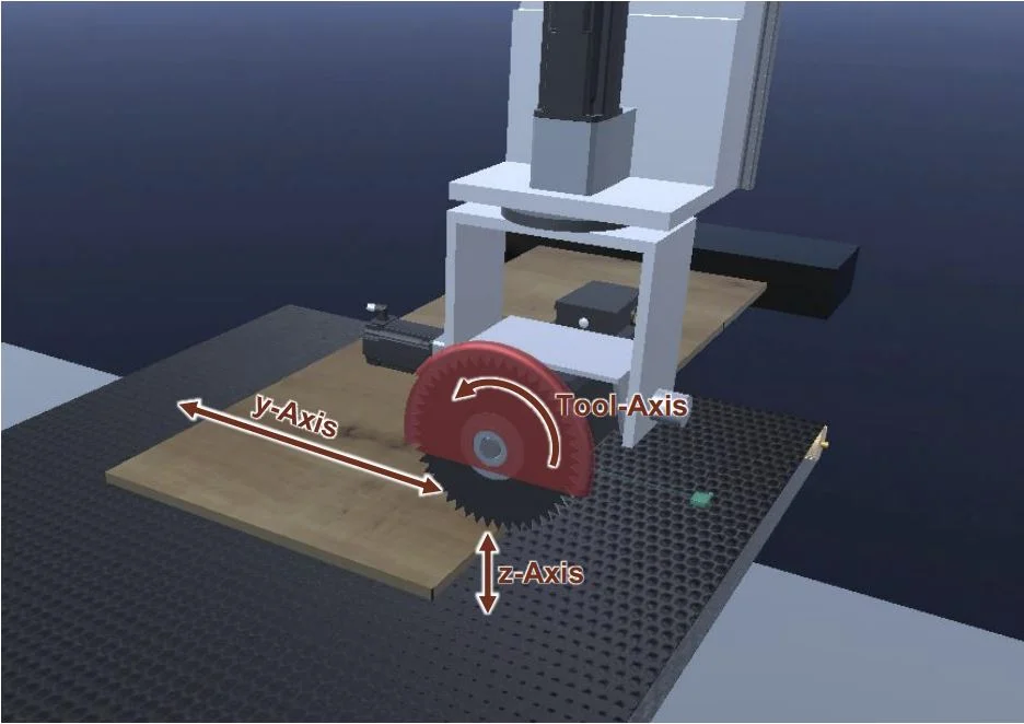
Below is a sample visualization of the process for a flying saw application. This visualization allows you to perform a very accurate simulation of material transport and cutting.
3. Codesys Environment and Softmotion Add-On
In every automation engineer’s career, there comes a time when it’s necessary to diversify the equipment used in automation projects. Siemens programming skills may not always be enough!
The Codesys environment is an excellent solution, as it allows you to operate devices from over 200 manufacturers (such as WAGO, Beckhoff, Weintek…). Additionally, you can learn to program servo drives using the built-in virtual axis simulator on your computer.
How do you simulate drive application programming systems?
- Install the free Codesys software – it comes with a time-unlimited license.
- Create a new project and a virtual axis.
- Write a program using PLC Open Motion blocks.
- Test the setup in the simulator without using a real PLC.
That’s it! Now you can implement your ideas from anywhere in the world.
If you’d like to learn how to complete all these steps quickly with our support, sign up for our free mini-course on servo drive programming. You’ll find video instructions that will help you understand the basics and save time.
What features does Softmotion simulation offer? The most important one is the ability to add virtual axes (rotational and linear). You assign a name to the axis, configure it, and quickly proceed to creating applications in the project tree structure. You can choose your preferred programming language from the IEC 61131-3 standard for task execution. In practice, some function blocks are handled in graphical languages like FBD, while the machine sequence is written in the textual language ST (Structured Text). This approach provides a clear and scalable solution.
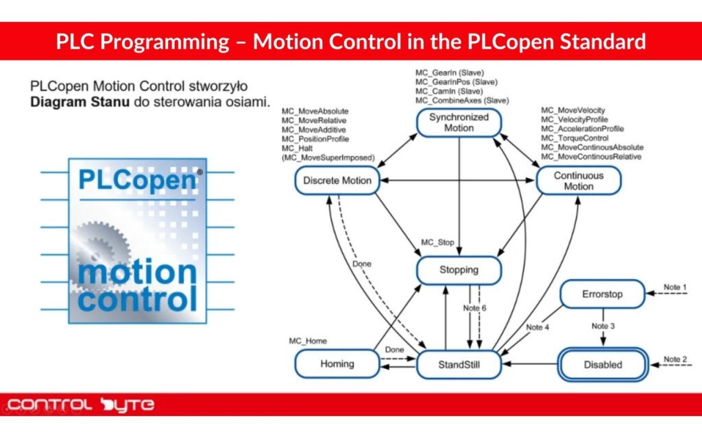
Automation is a dynamically evolving field. Every year, new automation components and software are developed. Manufacturers are competing to bring solutions to the market that significantly simplify work. Libraries are also being developed to handle complex processes using single “blocks.” Knowledge of the PLC Open Motion standard is essential in any motion control application. This standard provides a set of function blocks for configuring drives and executing specific movements. The FB blocks are interconnected in a structured way.
4. What Does a Sample Program Look Like in the Codesys Simulator?
Start by familiarizing yourself with the function blocks from the PLC Open Motion library. The first operation you need to perform is to power the axis using the MC_Power block. Simply connect the virtual axis to the block and assign variables to the Enable, bRegulatorOn, and bDriveStart inputs. After completing this step, you can move on to the first steps in motion control. In my experience, a key achievement for any beginner programmer is running the drive in JOG mode. In short, this instruction allows you to move the axis at a specified speed in continuous mode, which can be used, for example, for manual control of the axis.
The next step involves using the MC_MoveAbsolute and MC_MoveRelative blocks. In simple terms, these are used to perform relative movement (moving by a specified distance) and absolute movement (moving to a specified position). These blocks require a few additional parameters, but you’ll manage them without issues. You should also test the MC_Stop block, which is responsible for stopping the axis if another instruction is currently running.
A useful tool in Codesys is visualization, along with ready-made visualization templates. With just a few clicks, you can link function block instances and add symbols for rotational or linear axes. Then, all you need to do is upload the program to the simulator and enjoy your first working motion control program. Remember, all you need is your computer. There’s no need for a real PLC or servo amplifier.
5. 2D/3D Simulation of Multi-Axis Systems and Robots
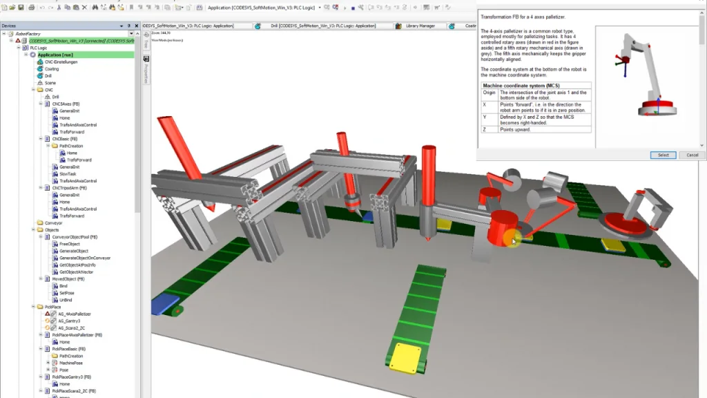
Codesys is a powerful tool that meets most of an automation programmer’s needs. In addition to controlling single axes, you can perform drive synchronization and use motion control profiles. But that’s not all. The SM3_Robotics library allows you to select an appropriate kinematic configuration and program robots and manipulators.
All you need to do is define the necessary axes (rotational, linear) in the project, then select an existing kinematic setup in Codesys. You have access to basic setups, such as a polar configuration consisting of a linear and a rotational axis. This lets you quickly create an application for transferring products from one conveyor to another.
An interesting option is the support for SCARA robots, which are great for product transfer and inspection tasks. In this case, you’ll need to define three parallel axes. You can quickly connect your configuration to visualization templates for the specific kinematic setup and test the programmed motion sequence.
That’s not all! The appropriate add-on allows you to create 3D simulations of production lines with robots and manipulators. This enables you to efficiently present your solution concept to a potential client and test the concept without needing a physical setup on the factory floor. This is known as offline programming.
6. Writing Sequences for Drives in the PackML Standard
Every automation engineer eventually faces the task of creating a motion control program from scratch. Each machine operates according to a specific algorithm. The sequence of program execution is particularly important in drive applications. You need to anticipate all possible movements of each axis and prepare the steps in the sequence accordingly.
I have to admit something. Initially, I struggled with designing a functional sequence. This was because I didn’t have access to a specific template to follow. I tried on my own to determine the best scenarios for my programs. Everything changed when a colleague introduced me to a certain standard…
Using the PackML Standard for Sequence Simplification
In most industrial facilities, machines operate according to predefined rules. Before writing the program, you should agree with your client on the machine’s operating concept. There is a tool that significantly simplifies your work—use the PackML standard!
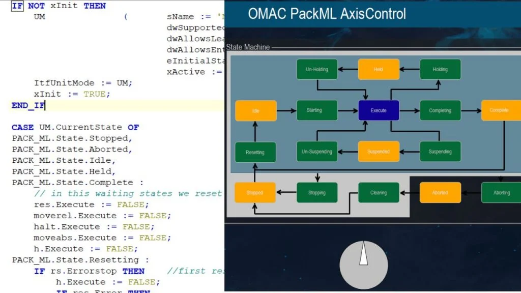
The PackML standard provides a sequence step template that you can use in Codesys. It includes various states: EXECUTE, ABORT, STOP, START, IDLE, etc. Each state is associated with different PLC Open Motion blocks. For example, the EXECUTE state represents production, meaning the drives need to be turned on and performing specified movements. The ABORT state handles the emergency stop procedure (MC_Stop block), and therefore the proper start procedure in the sequence must be followed to return to production.
PackML provides a template with states like EXECUTE, ABORT, STOP, START, and IDLE. Each state controls different PLC Open Motion blocks. For example, EXECUTE represents production, so drives need to be on and performing specific motions. The ABORT state manages emergency stop procedures (MC_Stop block), requiring a specific restart sequence to return to production. You can learn more about the PackML standard on our YouTube channel.
In Codesys, the sequence is usually written in the textual language Structured Text (ST). This provides full control over the program and enables quick modifications in the sequence. Each machine state has its own section in the program, where you specify particular instructions. An important element is the visualization template that displays the active state of the sequence. This approach speeds up your work and ensures that every movement of your drive is executed at the correct time.
7. Summary
The Fourth Industrial Revolution has reached not only industrial facilities but also training centers. Year by year, software that enables the simulation of automation systems is becoming increasingly accessible, allowing the training of competent engineering staff in a shorter time.
In the past, to learn the workings of a more advanced drive application, you had to test scenarios during prototyping or the final launch of a production line.
Today, a well-prepared online training course is all you need!
On your PC, you can run simulations of even the most complex drive systems and prepare applications without any physical equipment.
This creates incredible opportunities and opens the door to a higher level in the field of drive application programming in automation.
Thank you for reading! If you’re interested in learning more, explore our courses for in-depth training: Control Byte Courses.

