Analog vs Digital sensor in Control Systems
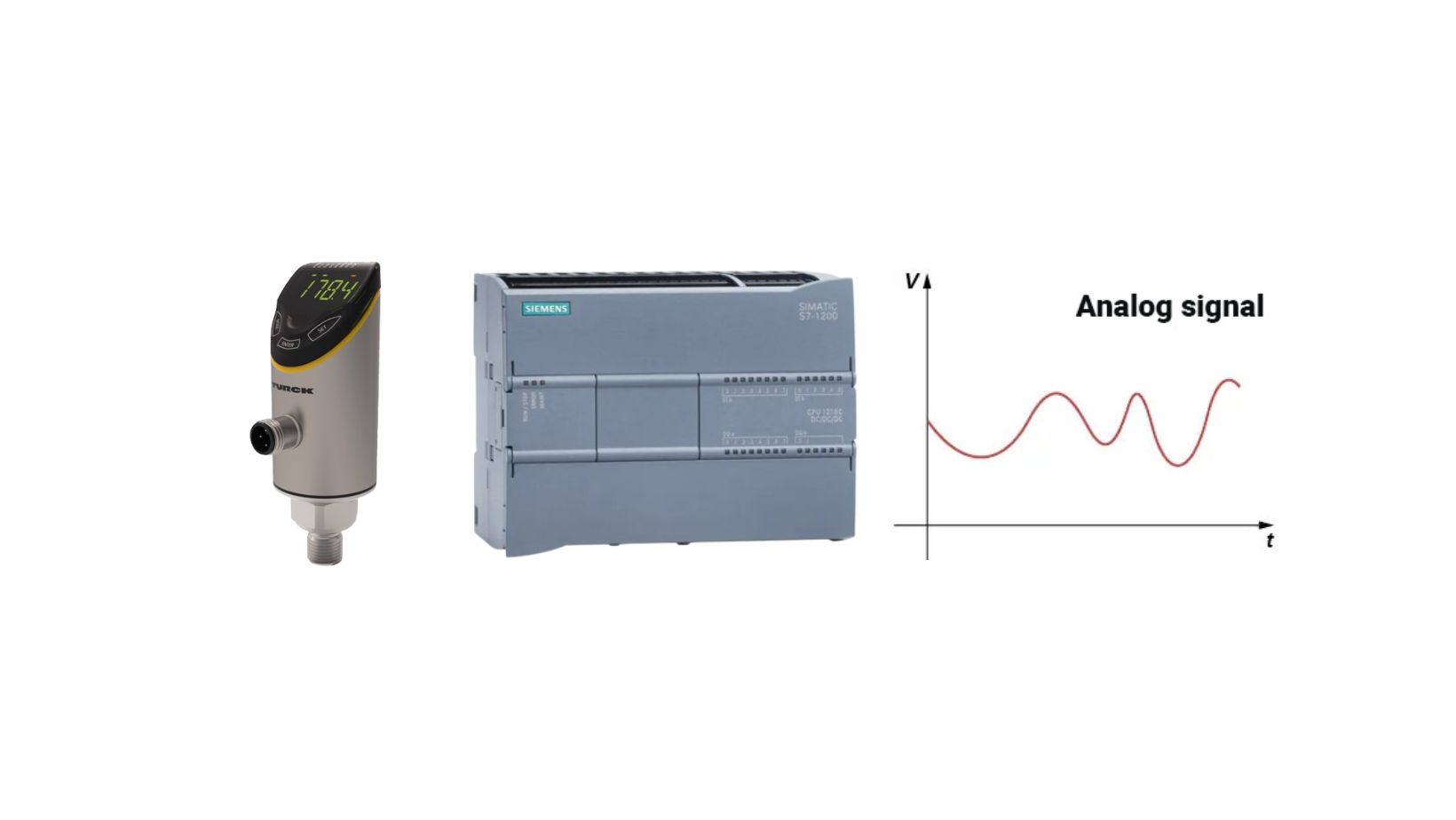
In the world of industrial automation, analog vs digital sensors play crucial roles in providing accurate information about various technological processes. Analog signals, for instance, deliver data on physical quantities like pressure, flow, level, distance, weight, density, concentration, and temperature. But how exactly do these sensor types differ, and what are the key aspects of each?
Difference between Analog and Digital signal
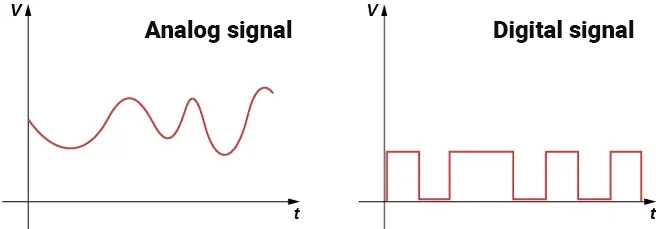
Analog Sensor: The Heart of the Measurement System – voltage
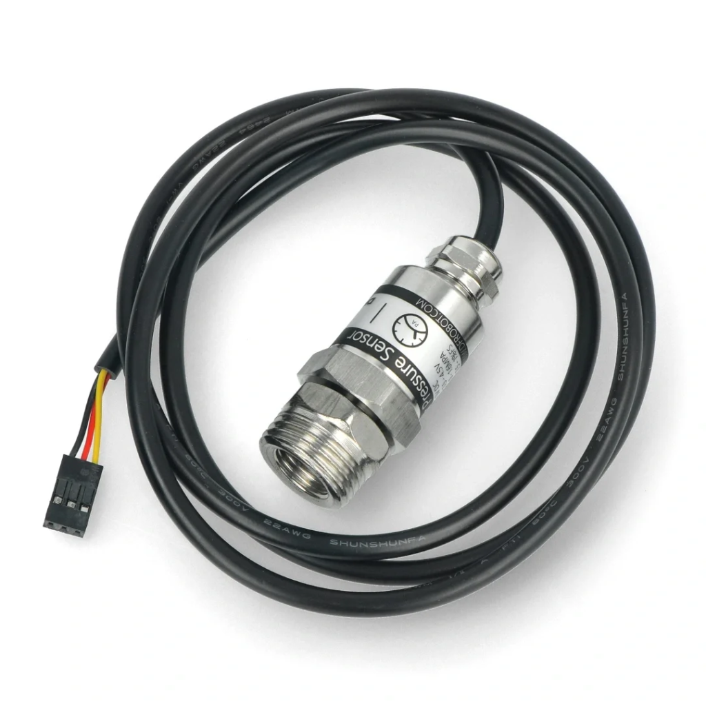
An analog sensor, also known as a transducer, is a device responsible for converting a physical quantity into an electrical signal.
In the industry, two electrical signal standards are most commonly encountered:
- Current signals:
- 4mA…20mA (standard range)
- 0mA…20mA
- Voltage signals:
- 0V…10V (standard range)
- −10V…10V
- 0V…5V
- −5V…5V
- 1V…5V
Which standard to Choose: 0-10V or 4-20mA?
The 4-20mA standard is more commonly chosen for several reasons:
- It allows for easy detection of circuit faults—if the value drops below 4 mA, it may indicate a problem with the wire or sensor.
- Current signals are less susceptible to electromagnetic interference compared to voltage signals.
- They can be transmitted over long distances (up to several hundred meters) without significant quality loss.
The 0-10V voltage signal is most often used within control cabinets and in measurement circuits where the wire to the transducer is a few meters long.
From Sensor to Controller: How Does the Measurement Circuit Work?
Let’s assume that the pressure in a tank is 6.1 bar. A pressure sensor [0..20mA] converts this physical quantity into an electrical signal, for example, 10.2 mA. The analog-to-digital converter (ADC) in the controller then converts this 10.2 mA signal into a digital value, such as 10,475. Finally, in the PLC program, this integer value is converted back into an engineering value (Real type), and the value of 6.1 bar is displayed on the HMI panel.
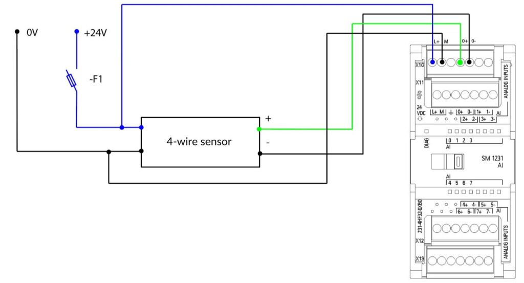
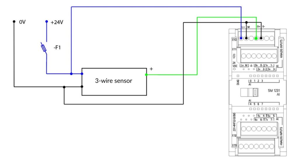
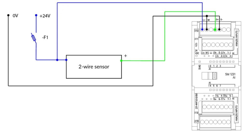
How Does an Analog Input Work in a PLC application
When an analog signal reaches the PLC, it is first sampled and converted into a digital value using an analog-to-digital converter (ADC). This digital value is then processed by the PLC program.
It is important to note that the quality and accuracy of analog inputs in a PLC can vary depending on the model and manufacturer of the controller. Therefore, it is essential to carefully review the technical specifications of the PLC before purchasing and implementing it in the system. Below are some example specifications for analog input modules for Siemens PLCs.
S7-1200 – Example Analog Input Modules
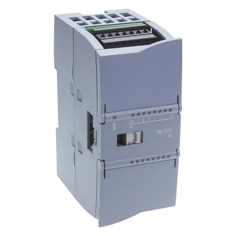
- SM 1231 AI4 U/I: 6ES7 231-4HD32-0XB0
- Input type: 4 voltage or current inputs +/-10 V, +/-5 V, +/-2.5 V, or 0-20 mA/4-20 mA
- Resolution: 12-bit + sign
- Processing time: approx. 40 ms per channel
- Approximate price: 850 PLN net
- SM 1231 AI4 HF U/I: 6ES7 231-5ND32-0XB0
- Input type: 4 voltage or current channels +/-10 V, +/-5 V, +/-2.5 V, or 0-20 mA/4-20 mA
- Resolution: 15-bit + sign
- Processing time: approx. 40 ms per channel
- Approximate price: 1350 PLN net
S7-1500 – Example Analog Input Modules
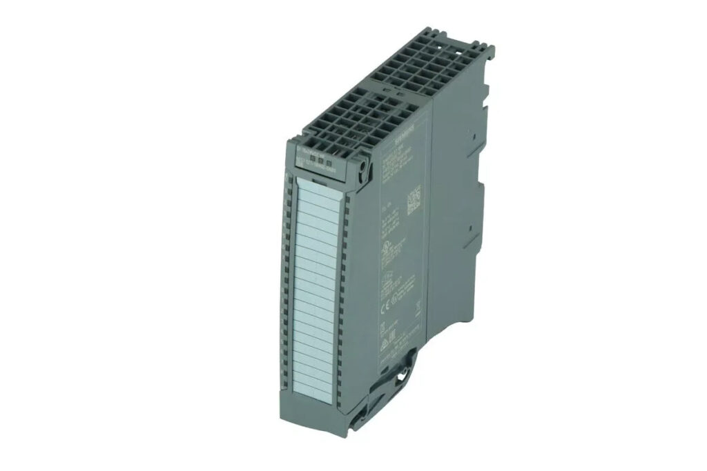
Example module for the S7-1500 controller AI 8xU/I/RTD/TC ST
- AI 8xU/I/RTD/TC ST: 6ES7 531-7KF00-0AB0
- Input type: 8 universal channels (voltage, current, RTD, thermocouple)
- Resolution: 15-bit + sign
- Processing time: approx. 9 ms per channel
- Approximate price: 3000 PLN net
- AI 8xU/R/RTD/TC HF: 6ES7 531-7PF00-0AB0
- Input type: 8 universal channels (voltage, resistance, RTD, thermocouple)
- Resolution: 15-bit + sign
- Processing time: approx. 4 ms per channel
- Approximate price: 3400 PLN net
Designing Measurement Systems
When designing an automation-system using analog measurements, several aspects must be considered:
- Measurement range:
Every measurement system has a defined range. Exceeding this range can result in improper operation or damage. - Accuracy and repeatability:
Some applications require high precision, while others can tolerate minor errors. - Type of physical quantity:
Choose a system specifically designed to measure the quantity of interest, such as temperature, pressure, acceleration, etc. - Environment:
Ensure the device is suitable for the environment, such as high humidity, temperature, or exposure to shocks. - Sensor type:
Active sensors require an external power source and often provide stronger signals, which can be beneficial in high-interference environments. Passive sensors do not need external power and are typically simpler, cheaper, and more reliable, but can be more prone to interference. - Cost:
Always consider the budget to ensure the selected system is reasonably priced for its functions and accuracy. - Interface and compatibility:
Ensure the measurement system is compatible with other devices in your setup and has the appropriate communication interfaces. - Longevity and reliability:
In industrial applications where the device will operate for a long time under harsh conditions, durability and stability are critical.
In summary, choosing the right measurement system requires analyzing many factors. It is crucial to understand your specific needs and requirements and match them with the appropriate system that will meet those needs in the most optimal way.
Active Analog Sensors
Active sensors, also known as powered sensors, require an external power source to operate correctly. They use this power not only to generate the output signal but also for internal operations, such as signal amplification or other processing functions.
Examples of active sensors:
- Pressure transducers: Convert pressure values into electrical signals, typically in the 4-20 mA range.
- Temperature sensors with current output: Such as those based on thermistors or RTDs with built-in signal amplifiers.
- Distance sensors with voltage/current output: Using ultrasound or light to measure distance and generate a proportional voltage/current signal.
Advantages of active sensors:
- They often provide integrated signal processing functions, such as amplification, filtering, or linearization.
- Generally offer higher accuracy and stability compared to passive sensors.
- Can be more resistant to interference, especially in industrial environments with high levels of electromagnetic interference.
Passive Analog Sensors
Passive sensors do not require an external power source to generate an output signal. Instead, they change their electrical properties in response to changes in the measured quantity.
Examples of passive sensors:
- Thermocouples: Generate voltage in response to the temperature difference between two different metals.
- Thermistors: Resistors whose resistance changes in response to temperature variations.
- Resistive position sensors (potentiometers): Change their resistance based on position.
Advantages of passive sensors:
- Simpler design and installation, as they do not require external power.
- May be more reliable in some applications due to the absence of complex electronic circuits.
- Typically cheaper to purchase and operate compared to active sensors.
PLC Analog Module Resolution
When analyzing the specification of a device with analog inputs, you may encounter various parameters, such as resolution, which can range from 6 to 16 bits.
Resolution determines how accurately an analog signal is represented in digital form. For example, in a 16-bit register, we can store an integer value from 0 to 65536 or −32768 to 32767 (with sign).
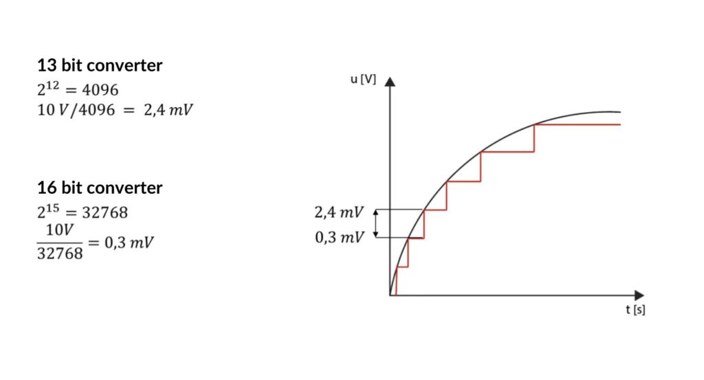
Let’s analyze a theoretical 13-bit and 16-bit converter (0-10V range).
A unipolar value measured by a 13-bit resolution module (= 12 bits + sign) is divided into a total of 212 = 4096 increments.
The smallest increment in the 0 to 10 V measurement range is 10V / 4096, which equals 2.4 mV.
If the resolution increases from 13 bits to 16 bits, the number of increments increases eightfold, from 4096 to 32768.
A 16-bit resolution module (= 15 bits + sign) provides an increment value of 0.3 mV.
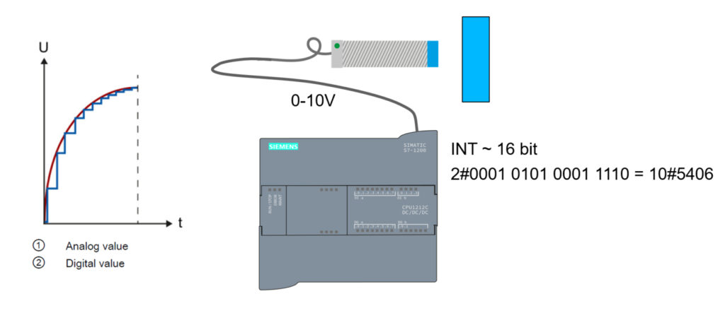
ADC Converter in Siemens Modules
The conversion is performed using an integrated ADC (analog-to-digital converter) in the analog input module. For the processor, this conversion always returns a 16-bit value, represented by a WORD/INTEGER variable in SIMATIC products. Whether the converter is 10, 13, or 16 bits, the ADC digitalizes the analog signal and approximates its value using a stepped curve.
Please note that the measurement voltage range of the module for the 0-10V signal is as high as 11.852V!
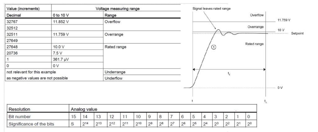
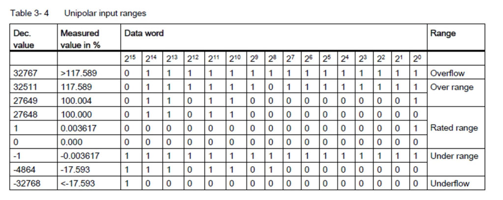
32768 increments are distributed across a voltage range of 11.852 V, which means that only 27648 increments are actually available for the measurement range resolution of 10 V. Therefore, the smallest value that can be represented is 0.3617 mV (see the table above).
If the signal exceeds the over-range or under-range limits, an ‘Overflow,’ ‘Over range,’ or ‘Underflow,’ ‘Under range’ error is diagnosed.
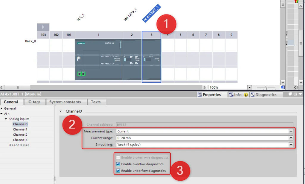
Converting an signal type (Analog) in Siemens TIA Portal
Module Configuration:
- Select the appropriate analog input module for your PLC, for example, for the S7-1200 (1)
- Configure the module in the TIA Portal software. Specify the signal type (voltage, current) (2) and range (for example, 0-10V, 4-20mA).
- Configure diagnostics (3)
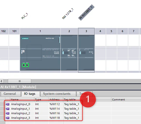
Reading values from the ADC
After configuring the module, the value read from the ADC converter will be available in the appropriate PLC memory register (1). For the given addresses, e.g., %IW112, you need to define a variable (e.g., AnalogInput_0) in the tag table. This value will be an integer (0-2727648) corresponding to the analog input signal.
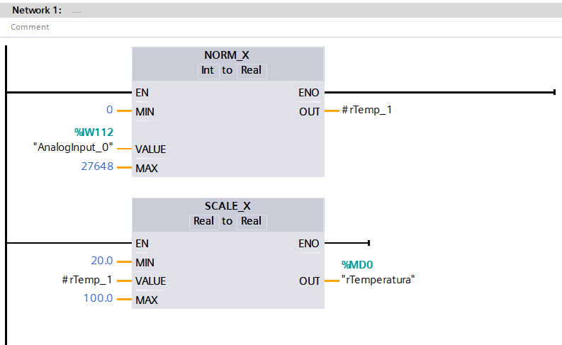
Value conversion:
- To convert the digital value to an engineering unit (for example, temperature, pressure), you need to apply a conversion formula. This formula will depend on the sensor’s characteristics and the signal range.
- For example, if you have a temperature sensor with a range of 20-100°C and an output signal of 0-10V, you can use the following formula:
Temperature (°C) = (ADC value / 27648) * (100-20) + 20
Where ‘27648‘ is the value in the register for a given ADC, corresponding to a 10V signal.
Implementation in the PLC program:
- Using the TIA Portal software, you can add program blocks that read the value from the ADC, convert it using the above formula, and store the result in the appropriate variable.
Interference in Analog Measurements
In reality, analog measurements can be susceptible to various types of interference, such as electromagnetic, thermal, or mechanical disturbances. These interferences can affect the accuracy and reliability of the measurements.
How to protect against them?
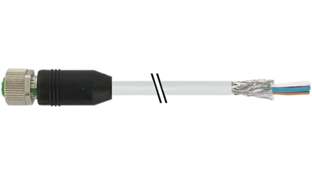
- Cable shielding
Shielded cables can significantly reduce the impact of electromagnetic interference on the signal. - Using filters
Filters can be used to eliminate unwanted noise from the signal. - Proper equipment placement
Avoid placing sensors and cables near sources of interference, such as motors or power supply cables.
Summary
Analog measurement systems play a vital role in industrial automation by providing precise information about various physical quantities. Understanding the principles of analog measurements, sensor types, and signal processing can significantly enhance the reliability and efficiency of these systems. Whether using active or passive sensors, and ensuring proper connection to controllers like Siemens PLCs, careful consideration of all factors—from signal types to environmental conditions—can lead to optimal system performance.
Thank you for reading! If you’re interested in learning more, explore our courses for in-depth training: Control Byte Courses.

