Introduction
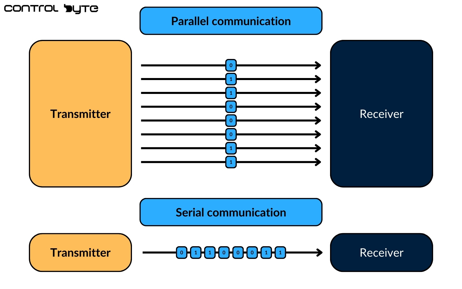
Serial communication, valued for its simplicity and lower hardware requirements, is a widely used communication method in various industries. Unlike parallel communication, where multiple data bits are sent simultaneously, serial communication transmits data bits sequentially, one at a time, along a single communication channel. Although parallel communication offers faster data transfer, serial methods like RS-232 remain popular due to their streamlined design.

The RS-232 standard is a cornerstone of serial communication, especially in industrial applications. Many professionals, particularly those with significant experience, frequently refer to RS-232 as the go-to serial protocol in workplaces.

Prerequisites
For a deeper understanding, familiarity with the “PLC Networking Basics Tutorial” is recommended. This background knowledge will support a better grasp of the principles covered here and enhance the learning experience.
Understanding RS-232 interface
“RS-232” stands for “Recommended Standard 232.” It outlines a protocol for serial data transmission and defines the physical and electrical characteristics for serial communication networks. While RS-232 is commonly referenced, it’s officially known as TIA-232, named after the Telecommunications Industry Association’s recommendations.

RS-232 Connectors
The RS-232 standard primarily uses DB9 and DB25 connectors, both of which have a D-shaped form and male/female connectors. Over time, the industry has favored the 9-pin version due to its smaller footprint and cost-efficiency, as many applications don’t require all 25 pins.


Pinout for the RS-232 communication standard
Given that the DB9 connector is the more common choice, this guide will explore its pinout in detail:
- TXD (Transmit Data): Transmits data to the receiving device.
- RXD (Receive Data): Receives data from the transmitting device.
- DTR (Data Terminal Ready): Signals that the transmitting device is ready to establish a connection.
- DSR (Data Set Ready): Indicates the receiving device is ready for communication.
- RTS (Request to Send): A signal from the transmitter requesting permission to send data.
- CTS (Clear to Send): A signal from the receiver granting permission to the transmitter.
- GND (Ground): Provides an electrical reference point.
- DCD (Data Carrier Detect): Signals that a remote carrier tone has been detected.
- RI (Ring Indicator): Indicates that the line is ringing, primarily used in modem applications.

RS-232 serial communication standard
Starting Communication
Begin by imagining two devices that need to communicate. For simplicity, consider one device solely transmitting data while the other only receives it. In practice, both devices can transmit and receive, but understanding one-way communication clarifies the concept, making it easier to apply to both directions.

The creation of data in the transmitter initiates the transmission process through a physical wire to reach the receiver. This data transfer relies on the transmit data (TXD) pin on the transmitter and the receive data (RXD) pin on the receiver. Connecting these pins establishes a critical pathway, ensuring a smooth flow of data from the transmitter to the receiver.

The RS-232 standard addresses situations where the presence of a receiver needs confirmation. How does it achieve this?
The RS-232 designers incorporated a dedicated control wire into the system to signal the presence of the receiver to the transmitter. This link, labeled Data Terminal Ready (DTR) on the transmitter’s side and Data Set Ready (DSR) on the receiver’s side, ensures that when connected and the appropriate voltage is set by the receiver, the transmitter is informed of the receiver’s availability, allowing data to be safely transmitted.

Transmission Speed and Data Rate
Another potential issue that may arise is the speed of data transmission from the transmitter to the receiver. If the transmitter sends data too quickly, the receiver may be unable to process it at that rate, resulting in data loss.

To address this, RS-232 includes a flow control
mechanism. Hardware flow control uses additional control wires: Request to Send (RTS) on the transmitter side and Clear to Send (CTS) on the receiver. When the transmitter is ready, it sends an RTS signal, and the receiver responds with CTS to confirm it is prepared to receive data. This RTS-CTS mechanism ensures efficient, reliable communication between devices.

Software Flow Control
In addition to hardware flow-control, RS-232 supports software transmission control. In this method, special characters (XON and XOFF) are used to regulate data transmission. The receiver signals its readiness to accept data by sending an XON character to the transmitter. If the receiver needs the transmitter to pause, it sends an XOFF character. Although software signal management is generally less reliable than hardware-based control due to the character-based signaling, it is adequate for many applications.


In the simplest RS-232 setup, data transfer between two devices requires only three wires: transmit, receive, and ground. The ground wire, known as Signal Ground (SG), provides a reference voltage for proper operation. With these three connections, basic RS-232 communication between two devices is successfully established.
In its simplest form, RS-232 communication requires only three wires—transmit, receive, and ground (Signal Ground, SG)—to establish a functional communication link.
RS-232 serial Cables and Device Types
RS-232 standards define different cable types for connecting various devices, including straight-through, null-modem, and crossover cables. Each cable type serves a unique purpose depending on the devices involved.
Practical Example of Device Connections
A typical example of RS-232 connectivity is using an IPC (Industrial PC) as the DTE to communicate with an HMI (Human-Machine Interface) acting as the DCE. This setup employs a straight-through cable, aligning each signal directly, which is ideal for standard RS-232 communication between a DTE and DCE.

Device Roles – DTE and DCE
In RS-232 communication, DTE (Data Terminal Equipment) devices like computers or terminals typically connect to DCE (Data Circuit-Terminating Equipment) devices, such as modems or other communication peripherals. This differentiation defines which device initiates and which one terminates data transmission.

Standard Straight-Through Signal Cable
When connecting a DTE device to a DCE device, a straight-through cable is used. This cable aligns each pin directly across to the corresponding pin on the opposite end, ensuring straightforward data flow between devices like a computer (DTE) and a modem (DCE).

Types of RS-232 Cables
The primary RS-232 cable types are straight-through, null-modem, and crossover cables, each used for specific device setups.
- Straight-Through Cable: Used for DTE to DCE connections.Null-Modem Cable: Allows direct communication between two DTE devices by reversing certain signal lines.Crossover Cable: Connects two DCE devices, such as two modems, by similarly reversing signal lines.

Null Modem Cable for DTE-to-DTE Connections
To connect two DTE devices directly (e.g., two computers) without needing a DCE device, a null-modem cable is required. This cable reverses the TXD (Transmit Data) and RXD (Receive Data) signals, allowing both devices to communicate directly. Additionally, it maintains continuity on pin 5 (GND) and manages handshaking signals (DTR/DSR, RTS/CTS) to ensure stable communication.

Crossover Cable for DCE-to-DCE Connections
Crossover cables connect two DCE devices, such as two modems, directly. Like the null-modem cable, the crossover cable reverses the necessary signal lines (TXD and RXD), enabling direct communication between devices that normally require a DTE in the setup.

Limitations of RS-232
Despite its widespread use, the RS-232 protocol has several key limitations:
Cable Length Restriction
One of the primary drawbacks of RS-232 is the limited cable length, which is capped at around 50 feet. Beyond this distance, increased wire resistance and voltage drops can disrupt signal integrity, reducing the effectiveness of data transmission.

Data Transfer Speed
RS-232 operates at relatively low data transfer rates, typically around 20 kilobytes per second. This slower speed limits its use in high-bandwidth applications, making it suitable only for applications where low-speed data transfer is sufficient.

Interference Issues
The RS-232 standard is vulnerable to radio frequency interference (RFI) and electromagnetic interference (EMI). These disturbances can come from various sources, such as nearby machinery or wireless communication systems. Such interference can degrade signal quality, potentially causing data corruption or complete loss of transmission.

These limitations impact the operational reliability of RS-232 cables, restricting their
Applications of RS-232
In industrial automation, RS-232 is favored for short-distance, point-to-point data connections where moderate data speeds are sufficient. Devices such as PLCs, HMIs, IPCs, robots, motor controllers, CNC machines, and similar equipment frequently use RS-232 for communication.

Conclusion
This overview has introduced the RS-232 protocol, covering its definition, connector types, pin configurations, and operating principles, along with hardware and software flow control methods. We also explored the various RS-232 cable types and typical device configurations, examined its advantages and limitations, and highlighted its role in industrial applications. With this understanding, RS-232 can be confidently applied to projects where it remains a reliable choice despite advancements in communication technology.
Thank you for reading! If you’re interested in learning more, explore our courses for in-depth training: Control Byte Courses.


