In a world where time is one of the most valuable resources, tools that allow for precise time management are essential. Time relays are a crucial part of this system, offering mechanisms to accurately set time intervals and trigger actions at strictly defined moments.
Despite their seemingly simple construction, time relays play a key role in ensuring smooth operations in diverse environments, from industry to smart home systems. By exploring their functions, design, and modern applications, we open the door to a better understanding and utilization of the potential these dynamically evolving devices bring.
Classification of Timer Relays
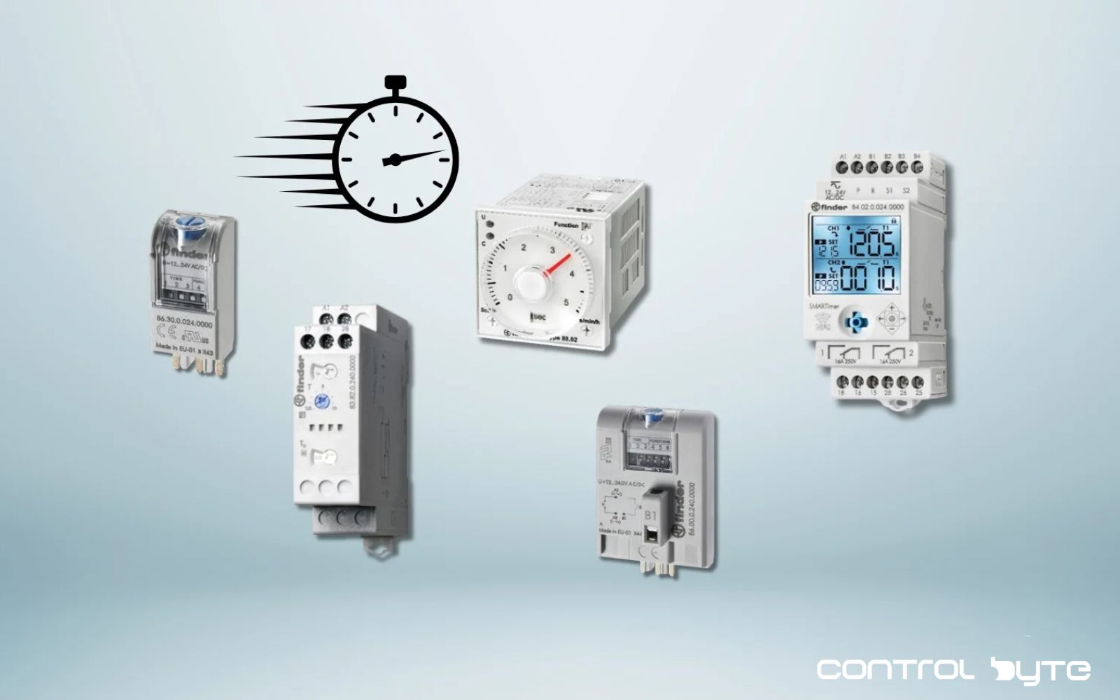
Finder time relays can be classified based on their functions and main parameters as follows:
Construction:
- Electromagnetic and semiconductor
- Modular/installation housing and industrial/sockets
- Number of contacts
Functions:
- Single-function
- Dual-function
- Multifunctional
- Special executions
Programming:
- Dials
- Dipswitches
- Application
Type of Load:
This division is not an official classification of time relays, but it effectively demonstrates how relays can be distinguished based on application needs.
Construction of a Time Relay
The construction of a time relay includes several key elements that work together to enable precise and accurate operation. The central element is a clock or timer, which may be an electronic circuit or a digital microprocessor capable of accurately tracking time in different units, such as hours, minutes, seconds, and milliseconds. Another important element is the relay or relays responsible for switching various electrical circuits depending on the time settings. Alternative control elements may include transistors or triacs used in semiconductor time relays. The main advantage of these relays is their quick response time, though in time control applications, this advantage becomes less significant, so they are not as commonly used in time relays. However, they still feature high switching durability (several million cycles), which makes them appealing to designers.
Inputs, Outputs, and Control Units
Input and output terminals for controlling other systems through the relay, and a control unit for programming specific time intervals and selecting particular functions. All of this is housed in a specially designed enclosure that provides protection from external factors as well as electrical insulation.
The type of relay enclosure is important when designing an electrical cabinet or making changes to existing projects. Modular enclosures are most often used in various building automation cabinets, while socket mounting is more commonly applied in industrial projects and control cabinets for various machines.
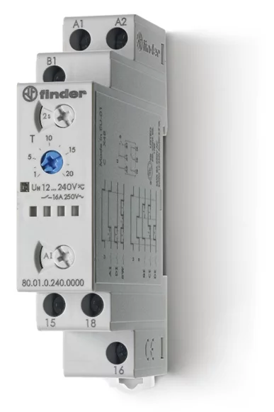
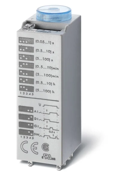
When comparing the above series, we can see how significantly they differ from each other. However, focusing only on the type of enclosure, the advantage of socket mounting lies in the ease of modernizing existing control systems based on time relays. It should also be noted that the 85 series can only be mounted in specific types of sockets.
What to Do if You Have Finder Relays but the Sockets Don’t Match the Series 85 Time Relay?
The 86 series comes to the rescue in this scenario. These are time relays in the form of modules that can be attached to sockets of other relay series.
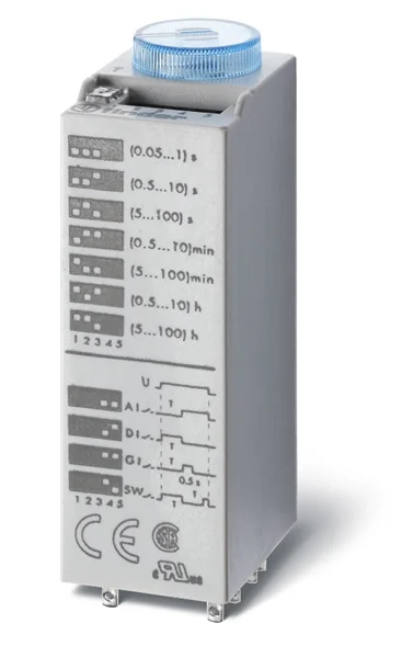
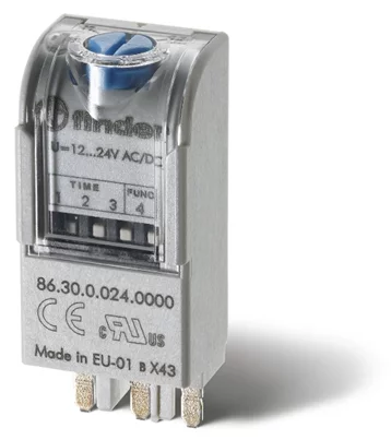
Time modules 86.30.0.024.0000 fit sockets 90.02, 90.03, 92.03, 94.P3, 94.P4, 94.02, 94.03, 94.04, 95.P3, 95.P5, 95.03, 95.05, 96.02, 96.04, 97.P1, 97.P2, 97.01, 97.02. Meanwhile, time modules 86.00.0.240.0000 fit sockets 90.02, 90.03, 92.03, 96.04. These modules were created because, in many cases, after a project has been created and approved, the control concept may suddenly change. By adding these in place of a protective module, a standard relay can be easily converted into a time relay, allowing for control concept changes without significant alterations to the project. Both relays are programmed using dipswitches and have two standard functions. The 86.00 module additionally has a START signal terminal and is equipped with six additional time functions.
Types of Contacts in Time Relays
Time relays are typically equipped with only one or two contacts, which is optimal in terms of production and functionality. However, time relays with more contacts are also available. Finder’s 85 series, for example, offers up to four switching contacts, allowing for time-based control of a large number of devices while conserving space in the control cabinet. Additional contacts offer functions such as PAUSE, START, and RESET. Their purpose is to streamline control of a given process and extend the lifespan of the time relay. A distinctive feature of Finder time relay contacts is that they all use AgNi as the standard material.
What if You Need to Activate Two Devices at Different Times with a Single Signal?
One solution is to use one time relay and one standard relay, which will solve the problem. However, Finder also offers time relays such as the 83.02 and 88.12 models, which feature one contact with a timing function and one contact that activates immediately. This allows for problem-solving, space-saving in the control cabinet, and cost reduction.
What Type of Power Supply Should Be Used? AC or DC?
Most Finder relays feature universal power supplies with PWM technology, allowing them to operate on either AC or DC power from 24 to 230 V without concern for specific values. This voltage flexibility broadens their range of applications and simplifies selection and design processes. Some series, particularly those designed for socket mounting, separate DC and AC voltages, supporting either 230…240 AC or specific DC values (12, 24, 48, 110…125) without polarity concerns.
The 83 series, housed in modular enclosures, meets rigorous standards, including EN 45545-2:2013 (fire resistance), EN 61373 (vibration and shock resistance, Category 1, Class B), and EN 50155 (temperature and humidity resistance, Class T1). These certifications make the 83 series suitable for demanding applications, such as in railway and maritime settings.
Programming Time Relays
There are several ways to program time relays, typically involving setting the time range, time setting, and function for the relay’s specific operation.
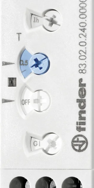
The most common method uses dials, found in series like the 80 or 83 series. The first dial sets the time range, which varies by series. For example, the 83.02 time relay offers ranges from 1 second to 10 days (1s-10s-1min-10min-1h-10h-1d-10d).
The second dial controls the time setting itself, with values specific to each series. For the 83 series, the settings range from (0.05…1)s to (0.5…10)d, while the 80 series offers (0.1…2)s to (1…24)h.
The third dial, available on certain relays, allows selection of contact behavior: activating both contacts according to the function or immediately upon power. The fourth dial sets the function; for instance, the GI function provides a Single Pulse.
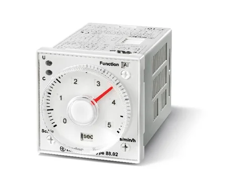
Dial adjustability varies, with options to set them using a screwdriver or, in the 88 series, adjust by hand.
Dipswitch Programming
In the 88 series, you can also see that the timing function and time range (sec, min, h) are adjusted with a screwdriver.
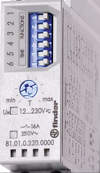
Of course, dials are not the only way to configure/program a time relay. Another method is using dipswitches. As shown in the image below, switching positions can adjust the function and time range settings. They are still in use because, without the need for advanced software or communication interfaces, the relay can be easily configured according to the specific application requirements. It’s also easy to notice tampering with the relay, as the position of the switch indicates such changes.
Smartphone Application Configuration
The last configuration method Finder offers for time relays is using a smartphone application for the 84 series to select the function and time settings.
Manually setting the function, range, and activation times sometimes requires several manual adjustments to achieve the required accuracy. The Finder Toolbox application simplifies time relay configuration by providing clear, graphical descriptions of each function. Users can set activation times to within tenths of a second, ensuring reliable operation.
Adjusting Time Settings Externally on Time Delay Relays
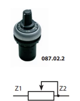
Finder offers a solution for this as well. Relays from the 83 series, specifically models 83.02 or 83.52, allow for connecting an external linear potentiometer (10kΩ / ≥ 0.25 W). Using an external potentiometer enables automatic adjustment of the internal time relay settings. This potentiometer can be mounted on the door of the control cabinet and connected to terminals Z1 and Z2. Note that the potentiometer’s supply voltage will be the same as the relay’s supply voltage.
Functions of Time Relays
Finder offers both single-function and multifunctional time relays. Multifunction relays are versatile and useful when multiple functions are needed. Single-function relays, on the other hand, are optimal if only one function will be used, eliminating the need for specific function settings and reducing potential unintended interference with the relay. The most common time relays on the market feature several time functions, usually up to six. However, the 84 series time relay allows programming up to 30 different time functions on each of its two channels.
Some of the most popular functions include delay-off or delay-on. In this case, after activating the delay timer, the relay counts down the set time before disconnecting or connecting the circuit.

Another function is the start signal pulse, a one-time control signal activated upon relay activation. After receiving the start signal, the delay time starts, and after this time elapses, the relay closes the output contact. The reset occurs after the set time. This short activation pulse can vary in length, depending on the setting.

What if We Want to Repeat Pulses Cyclically at Specified Time Intervals?
An asymmetric pulsing function is useful in this case. It can start a cycle from either the activation phase or the pause phase, depending on the configuration. If started by the activation phase, an impulse is immediately generated by closing the output contact, and subsequent impulses are repeated cyclically as long as power is supplied to the time relay.

Another useful function is start-signal delay-off. When the start signal is activated, the relay’s output contact immediately closes. Upon receiving the start signal, the relay begins counting down the specified delay time. After this period, the relay’s output contact opens.

What if You Need to Time-Control the Activation of a Three-Phase Motor?
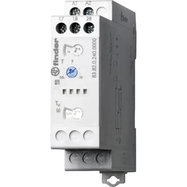
The 83.82 (or 80.82) relay offers a star-delta switch function that supports controlling contactors connected to three-phase motor windings. This relay allows users to adjust the break time between switching modes and set specific time intervals. It also includes terminals for connecting delta and star mode circuits. By reducing the number of contacts, the relay simplifies the process and eliminates the need for separate power supplies to each output. Users only need one power supply, making installation and operation easier.

These functions are just a few of the most frequently used ones. Finder provides a broad range of time relays with various functions, detailed in user manuals and indicated on their enclosures.
Load Capacity of Time Relays
Selecting a time relay based on its nominal contact load is critical for ensuring the proper operation of the entire system. Finder offers a broad range of time relay series, and thus their contact parameters vary, allowing for appropriate selection based on the application. The most common solution is a time relay that switches a nominal current of 8 or 16 A. However, this does not mean that the relay will operate incorrectly at lower loads. The information in the catalog regarding electrical durability (i.e., the number of switching cycles for the circuit) is always provided for nominal voltages and currents. According to the table, for DC loads, the relay also maintains a capacity of 16A at 24V DC, which is not always self-evident. If the time relay controls contactors, solenoid valves, or electromagnets, switching power should be selected based on AC15 ratings.
| Number of contacts | 2 P |
| Rated/current switching current (A) | 16/30 |
| Rated voltage/max. switching voltage (V AC) | 250/400 |
| Max. switching power for AC1 (VA) | 4000 |
| Max. switching power for AC15 (230 V AC) (VA) | 1000 |
| Single-phase motor load (230 V AC) (kW) | 0.55 |
| Max. DC1 current: 24/110/220 V (A) | 16/0.3/0.12 |
| Min. switching power (mW (V/mA)) | 300 (5/5) |
| Standard contact material | AgNi |
The Most Versatile and Modern Time Relay
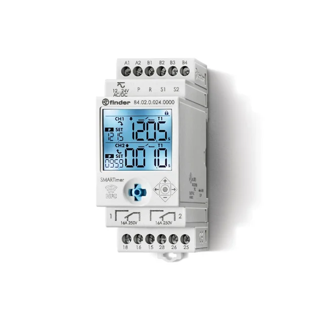
If you need a versatile time relay with comprehensive functions and extensive time-setting options, the 84.02 is an excellent choice. This intelligent device includes two independent channels and allows the creation of specialized functions by combining up to 30 functions per channel. It’s easily programmable via an NFC-enabled smartphone through the Finder Toolbox app or by using a joystick.
Each channel has its own START signal, enabling two independent time relays, each with access to one of 30 possible time functions. The relay also supports PAUSE and RESET signals on both channels, so you can pause the system by applying a signal to the P (Pause) input and resume by removing it. A RESET function allows the system to be reset by applying voltage to the R (Reset) input, ensuring quick process stoppage when needed.
The 84 series relay includes a backlit LED display, which simplifies reading information during programming and operation. The display shows the set time, current time, countdown, and output status. This relay offers high precision and a wide time-setting range, from 0.1 seconds to 9999 hours.
Operators, maintenance staff, or service personnel frequently adjust “standard” time relay settings. These changes can destabilize the system and require time-consuming troubleshooting to restore stable operation. To avoid unnecessary adjustments, the 84 series time relays include a PIN lock option to prevent unauthorized configuration changes, which may occur due to error or deliberate attempts.
Applications of Time Relays
Due to their multifunctionality, time relays can be used almost anywhere time-based control is needed. However, they are most commonly used for automating various production processes. They can control machine cycles, precisely synchronize different production stages, and ensure optimal resource use. By programming maintenance intervals, replacements, or service, safe working conditions can be maintained, minimizing risks of failures or accidents and improving workplace safety. By managing device working time and rest periods, the risk of overload is reduced, resulting in increased reliability and equipment durability.
In building automation, time relays play a crucial role in ensuring comfort, energy efficiency, and safety for residential, office, or public buildings. In buildings with green areas, they can be used to control irrigation systems for gardens or lawns, automatically watering at specific intervals, adapting to plant needs and weather conditions.
Summary
It is easy to see that time relays are essential tools in electronics and automation, enabling precise time control in various electrical systems. Their versatility and adaptability to different needs make them a key component in the rapidly evolving field of technology.
Technological advancements, including those in time relay technology, open up limitless possibilities. Thanks to time relays, we can increase work efficiency and productivity and enhance comfort and quality of life. Automating processes with time relays saves time and effort, allowing us to focus on more creative and valuable activities.

