Relays Through the Years
The dynamic development of industrial automation has led to some components evolving significantly in terms of design, function, and application. This evolution is notably true for relays. Years ago, relays were indispensable for creating control logic. However, with the advent of programmable relays and PLCs (Programmable Logic Controllers), building control systems exclusively based on relays has become largely impractical.
Role and Function of Industrial Relays in Automation Systems
Manufacturers offer thousands of versions of electromagnetic and solid-state relays. For example, Finder’s range includes sub-miniature and miniature relays used in electronic circuits, larger relays for control panels, and powerful Series 68 relays capable of switching currents up to 100A at 400 VAC on a single contact.
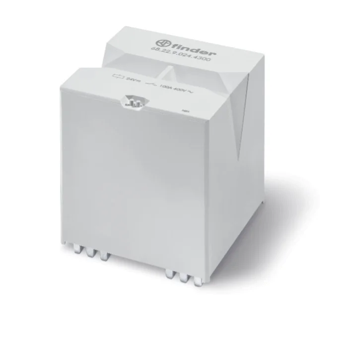
Learn more about these relays here: https://www.findernet.com/pl/polska/series/seria-68-przekaznik-duzej-mocy-100a/
This article will focus on relays used in automation systems and installed in control panels.
Electromagnetic and solid-state relays must meet specific parameters to ensure reliable operation in control systems. Based on their function and main parameters, relays can be categorized as follows:
- Switching Function
- Contact load capacity
- Impulse current resistance
- Electrical and mechanical durability
- Reliability
- Isolation Function
- Minimum switching power
- Insulation properties
- Electrical and mechanical durability
- Size
- Logical Function
- Features
- Programming method
- Reliability
- Safety Function
- Safety categories
- Contact configuration
- Load capacity
While this categorization is unofficial, it helps clarify the relay series suited for different applications. This article elaborates on the switching and isolation functions, with logical and safety functions to be addressed in future publications.
Switching Function of General Purpose Relays
To understand the switching function, let’s start with basic relay parameters, such as contact configuration, contact material, and the differences between electromagnetic and solid-state relays.

Electromechanical Relay (EMR)
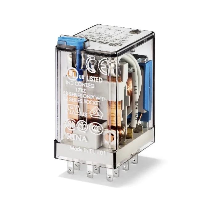
Electromagnetic relays are mechanical switching elements that change their operating state through mechanical parts.
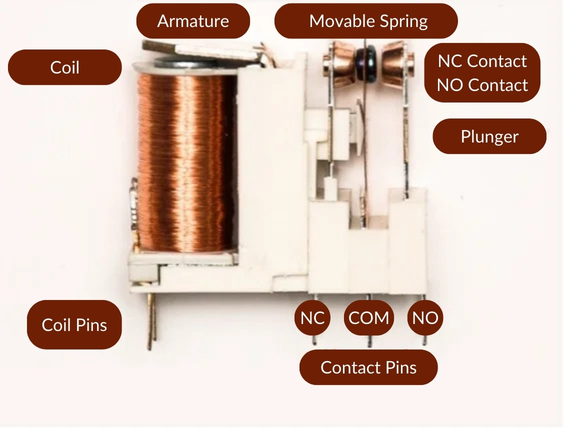
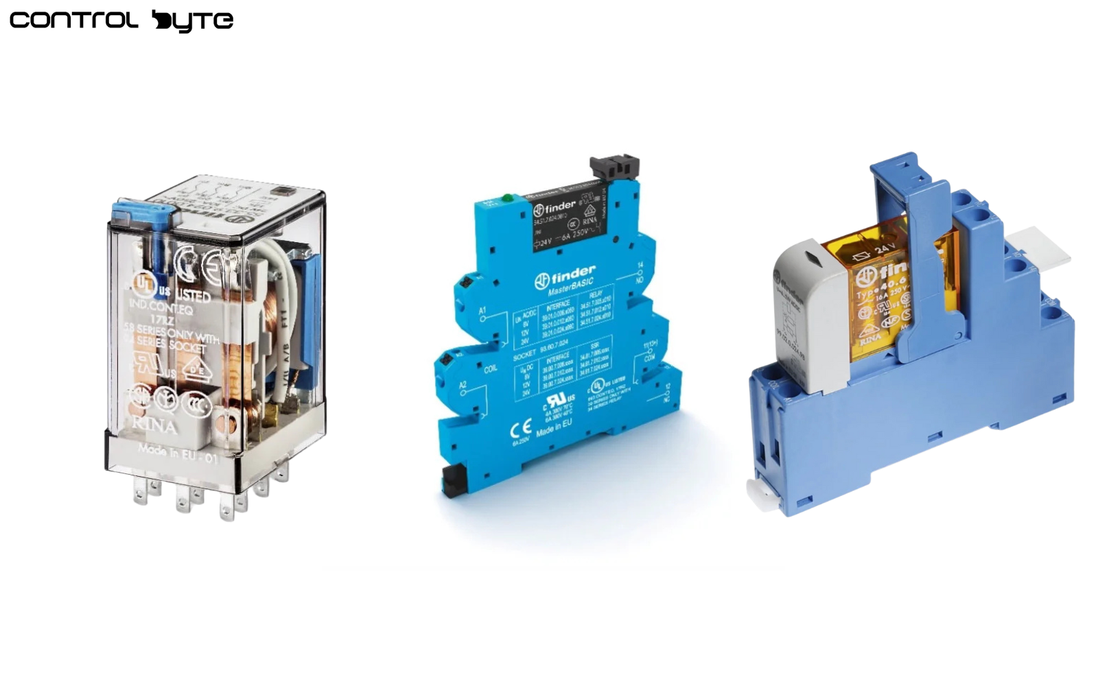
Based on the image above, we can distinguish several components:
- Relay coil
- Relay contacts
- Coil and contact pins
- Mechanical elements – such as the armature, pushers, and anchors (depending on relay type and series)
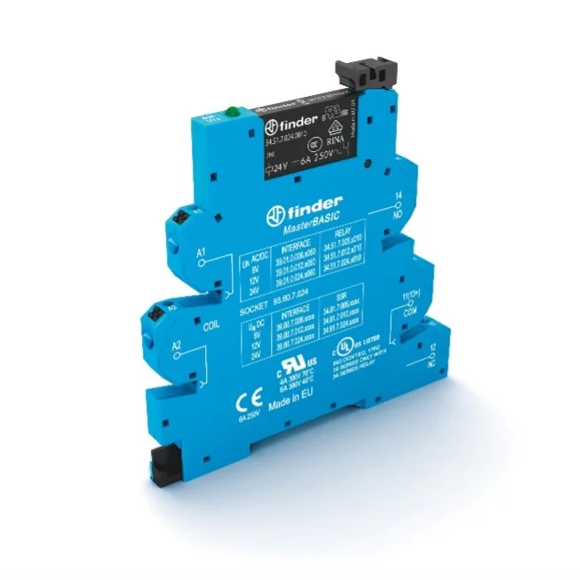
Monostable and Bistable Relay Types
When voltage is applied to the relay coil, the contacts change state (turning on or off, depending on configuration).
Bistable Relays
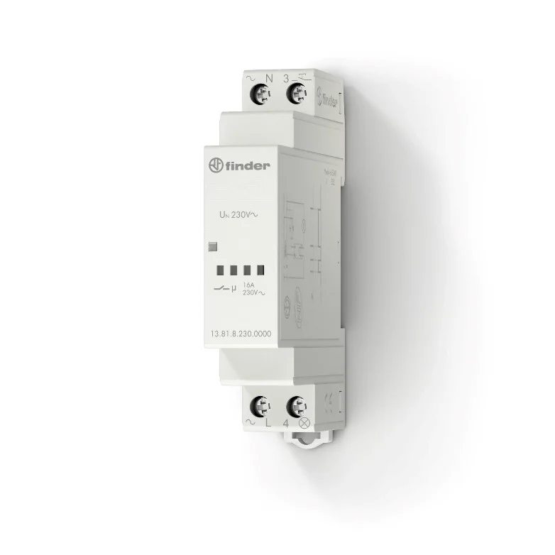
Bistable relays change their state upon receiving a control signal and retain their position even after the control signal fades. Another state change occurs upon receiving the next proper control signal or supply value. Types include:
- Impulse relay
- Mechanical bistable relay
- Electronic bistable relay
Advantages of Electromagnetic Relays (EMR)
- Universal voltage switching capacity across contacts
- Surge resistance
- Provides galvanic isolation between the coil and contact circuit
- No leakage currents
- Excellent power-to-size-to-cost ratio
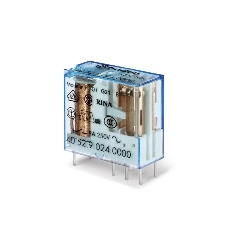
Disadvantages of Electromagnetic Relays
- Limited electrical and mechanical lifespan
- Low resistance to contact welding in basic versions if contact material isn’t properly chosen by the designer
Solid-State Relay Applications in Control Systems
In SSRs, the state change occurs through a semiconductor junction, with distinct control and power circuits. The output state changes upon supplying an appropriate control signal (often voltage) to the control input. SSRs are called relays because they contain a single contact gap in the control path.
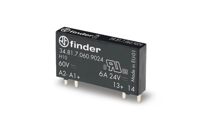
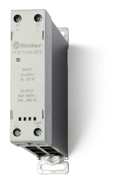
Due to varying controlled voltages (DC or AC), there are two primary types of output circuits:
- Transistor for DC voltage control
- Triac for AC voltage control
Based on sinusoidal voltage characteristics:
- Zero-crossing switching – the most popular option, reducing inrush currents
- Instant switching – best for applications where response speed is critical
Advantages of Solid-State Relays
- Extremely high switching durability (several million cycles)
- Continuous operation capability
- Zero-voltage switching
- Ability to switch high-load circuits
- Silent operation
- Fast response time
Disadvantages of Solid-State Relays
- Sensitive to high temperatures
- Heat dissipation is required during operation, typically through heatsinks or fans
- Leakage currents
- Lower surge resistance than electromagnetic relays
Contacts – Configuration, Selection, and Applications
Coding systems for various standards are provided in the technical manual from Finder (EU – European; D – German; GB – British; USA – American). Familiarity with these is beneficial due to the diversity of documentation encountered.

Relays commonly found in automation systems are available with 1, 2, 3, or 4 poles, often equipped with changeover contacts. Their high versatility and simple operation allow technicians to choose between NC (Normally Closed) or NO (Normally Open) contacts.
From the perspective of control system reliability, the durability of relay contacts is crucial. Before examining the electrical and mechanical durability of relays, it is essential to consider the materials used for coating the contacts, as illustrated in the table below. The longevity of a relay often hinges on selecting the right contact material.
The most widely used material is AgNi (silver-nickel), a versatile option due to its low minimum voltage, current, and power requirements, as well as its capacity to switch small resistive and capacitive loads. However, utilizing AgNi contacts has its limitations, particularly in applications involving high inductive or capacitive loads.
A contact material that is gaining traction is AgSnO₂ (silver-tin oxide). Although it may not excel in signal transmission, it offers excellent resistance to sticking and enhanced durability for both inductive and capacitive applications.
Gold-Plated Contacts are optimal for transmitting very low voltage, current, and power levels. These contacts also boast the advantage of being resistant to oxidation, making them particularly suitable for standby circuits or applications where the relay remains inactive for extended periods.
For many years, AgNi has been the predominant choice for contact material, providing moderate resistance to capacitive and inductive loads. However, it is increasingly insufficient to satisfy the demands of certain elements that relays are required to switch on and off effectively.
Switching Capacity Comparison between Standard and Reinforced Contact Materials
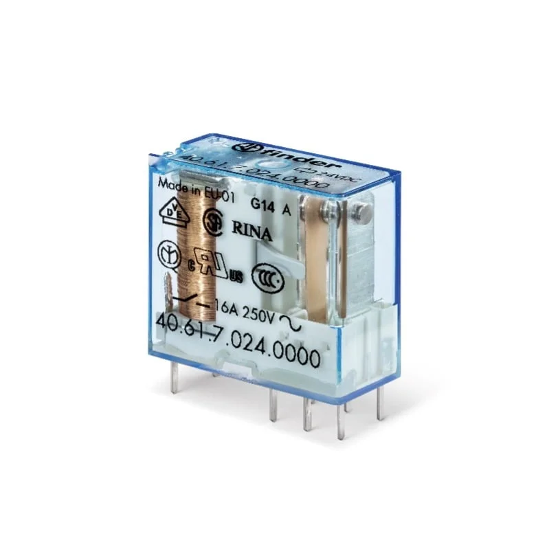
To illustrate, let’s consider the Finder Series 40.61.7.024.0000 relay, which has a single changeover contact made from AgNi. Its switching capacity parameters are as follows:
- Nominal current / Maximum switching current: 16A / 30A
This means the relay can handle a nominal current of 16A during operation, while the inrush current can reach 30A. But for how long can the relay withstand this nearly doubled load? Finder’s product catalog specifies:
“The maximum current that can flow for (≤ 0.5 seconds) without permanent damage to the contacts (duty cycle ≤ 0.1) due to heat buildup.”
This indicates that the relay, with AgNi contacts, can safely withstand an overload for no more than 0.5 seconds without adversely affecting the contact integrity.
When dealing with impulse currents exceeding 30A, reinforced contact materials like AgSnO₂ (silver-tin oxide) are preferred. This material can handle higher temperatures, preventing contact welding.
Capacitive loads generate impulse currents that are often multiples of the nominal load current. Consequently, the moment of engagement is critical, as it can lead to contact welding in the relay.
To illustrate capacitive loads, let’s look at the current waveform for a LETHE LMP-G60 domestic lighting fixture: 9.5 W, E27.
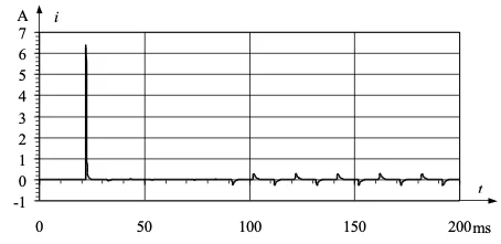
During steady operation, the bulb consumes minimal current, but at switch-on, it produces a “peak” current several times the nominal. Such a light fixture exemplifies a capacitive load, generating a large inrush current at start-up despite low steady-state consumption. A similar product with higher power demands could yield impulse currents of several tens or hundreds of amps at switch-on.
Returning to the 40.61.7.024.0000 relay, equipped with AgNi contacts, if we replace the contacts with reinforced AgSnO₂ material, the product code changes to 40.61.7.024.4000, and the relay’s switching parameters are notably improved. For example, Finder’s Series 40 documentation states:
“With AgSnO₂ material, the peak current is 120 A -5 ms (for 40.61) and 60 A -5 ms (for 40.52) on the normally open contact.”
This demonstrates that reinforced contact material significantly improves switching capacity and impulse current resistance, which is essential for handling capacitive or inductive loads. This principle also applies to other electromagnetic relay series, especially power relays, where impulse current resistance can reach up to 300 A.
Relay Durability in Electromechanical and Solid-State Designs
Electromechanical components have inherent limitations in durability due to natural wear and tear on moving parts. When operating at nominal parameters, two main factors restrict their lifespan: electrical durability and mechanical durability.
Electrical durability: The number of cycles a relay can perform at its rated load or other specified load types.
Example: The Finder 40.61.8.230.0000 relay, or its socketed version 48.61.8.230.0060 with varistor protection, has a nominal coil voltage of 230 VAC and a rated load of 16A at 250V AC1.
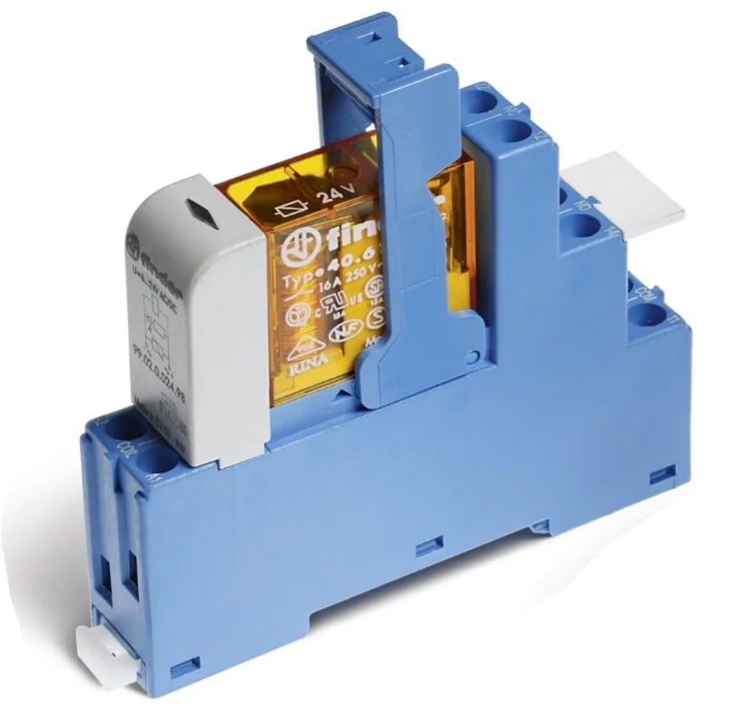
he product sheet states that its electrical durability is 100,000 cycles. According to Finder’s catalog, this means the normally closed contact can handle 16A at 250V AC1 (resistive load) for that many cycles, regardless of ambient temperature within catalog parameters.
Mechanical durability: The declared number of cycles a relay can perform without contact load, generally ranging from 1,000,000 to 10,000,000 cycles, depending on the product type and manufacturer.
Correlation Between Electrical and Mechanical Durability of Relays
In control applications, oversizing is common practice. But how can we determine if the oversizing is excessive or if the relay will fail before the warranty or maintenance cycle?
There are two approaches: conduct switching tests on a suitable group of components (if the load is not cataloged) or use correlation charts and correction parameters.

For example, the Finder Series 40 relay can achieve 100,000 cycles at 16A, but if the current through the contacts is reduced to 8A at 250V AC1, its switching durability increases to 250,000 cycles.
Isolation Function of Control Relays
In modern automation, electromagnetic relays often provide isolation, protecting the core control unit (such as a PLC) from input and output signals. The number of PLC I/O signals varies with system complexity, ranging from a few in small programmable relays to hundreds in advanced industrial controllers.
Relays ensure galvanic isolation between the control circuit (coil) and the execution circuit (contacts). For example, a 5 VDC signal can energize the coil and close contacts to pass a 400 VAC signal. Galvanic isolation provides a safe gap between circuit parts that prevents interference.
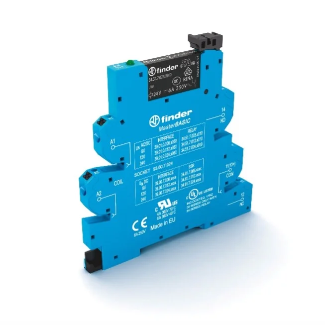
What is the value of galvanic isolation in relays?
The value of galvanic isolation must be provided by the respective relay manufacturer. What is the value for the 6.2mm interface relay, model 39.01.0.024.0060?

The test voltage is 6 kV, while the insulation strength is 4000 VAC. These parameters make the 6.2 mm series 39 interface relays an excellent choice for isolating input and output signals, as they can protect the PLC controller from external signals.
Why Use Safety Relays for Signal Isolation?
As mentioned before, the number of input and output signals can reach hundreds. Depending on the arrangement of control wires, wiring errors, short circuits, or voltage surges caused by lightning strikes or the switching on and off of high-power loads in control circuits, voltage levels can arise that may damage the control system. In such cases, the relay’s role is to “take on” such events, like short circuits or surges.
If the relay is damaged, it can be replaced quickly, as replacing a relay in a socket takes just a few seconds, and these are available at both physical and online distributors. Even replacing the socket is straightforward since it is mounted on a TH35 rail, making it easily accessible. Therefore, relays serve as an excellent protective layer, as damage to one of the controller’s inputs or the entire controller itself can halt the production process for at least a few hours (assuming there’s a backup controller with the program loaded) or even a few days if there’s an issue with availability of the controller, program, or technician.

Addressing Voltage Induction in Long Wire Runs with Series 39 Interface Relays
When the length of wires from various external sensors is significantly greater than in a standard industrial setting, a phenomenon known as a “long line” may occur. Simply put, this is the induction of voltages on control wires. This phenomenon is often encountered in mining, mining machinery, cranes, or lifts, where the voltage is typically 120 or 230 VAC (24 VDC is not used due to voltage drops). Voltage induction in control wires is undesirable in the control system, as the controller might receive a signal from a sensor when, in reality, no motion or object has been detected by the sensor, resulting in the controller receiving incorrect information, disrupting the entire control system.
An excellent solution to this issue is the series 39 interface relay, which was designed specifically to counteract the long-line phenomenon.
The following table shows the operating ranges for the coil of a standard series 39 interface relay:

and data for relays designed for long-line applications:

The voltage range for the coil supply remains consistent for both standard coil relays and those designed for long-line applications. This range is essential for the relay coil to operate the contacts effectively. For relays with a nominal coil voltage of 125 VAC, the operational range is from 88 to 138 VAC, while for a nominal coil voltage of 230 VAC, it spans from 184 to 264 VAC. However, the most critical parameter to consider is the dropout voltage, which indicates the voltage level that is too low for the relay coil to maintain its closed state.
For a standard 230 VAC relay coil, the contacts are expected to drop out at 23 VAC. In contrast, for relays intended for long-line applications, the dropout voltage can reach 72 VAC, significantly higher than the standard version. This feature makes these relays particularly effective at isolating signals from long supply and control lines. Series 39 relays, equipped with an internal circuit, help minimize residual and inductive currents, thus preventing contact dropout when such currents are present; they are designed for supplies ranging from (110–125) V AC/DC to (230–240) V AC.
Summary of Relay Types and Applications
catalog at Finder. Over time, these relays have evolved significantly in construction, role, and functionality, adapting to the changing demands of various industries.
This article focuses on two critical functions of relays: switching and isolation, particularly in selected electronic circuit applications. Finder offers a wide range of relay series and thousands of configurations tailored to meet the specific needs of different markets. Today’s high standards in sectors such as medical, marine, and mining present manufacturers with the challenge of adapting their products effectively.
Are Finder relays, known for their robust design and reliability, suitable for modern applications? Based on the information presented, they certainly meet today’s stringent requirements. The components fulfill the precise specifications necessary for various processes within automation systems. Moreover, a comprehensive certification base across diverse sectors and regions enables Finder products to be utilized in numerous applications, including those in demanding environments.
Thank you for reading! If you’re interested in learning more, explore our courses for in-depth training: Control Byte Courses.

