Wiring a 3-Phase Motor Terminal Box for Star-Delta Starter Control
The terminal arrangement mirrors what was previously described for motor windings, with a slight variation. For instance, in the motor shown below, three terminals with incoming power are labeled U1, V1, and W1. The lower terminals, however, differ slightly from the standard winding schematic.

In the schematic, the lower ends are labeled U2, V2, and W2,

but on the motor’s terminal box, they appear as W2, U2, and V2.

This configuration serves as a typical schematic for a three-phase motor’s terminal box. With these winding terminals, if you want to activate the motor in a star connection, you can connect these three junction together, as previously explained.

If starting the motor in a delta-connection, you can link U1 to W2, V1 to U2, and W1 to V2, following the steps covered earlier.
Automating the Switch from Star to Delta Connections with Contactors
To limit the high initial current of a three-phase motor, it’s best to start the motor in a star connection. This star configuration reduces the inrush current, protecting the motor windings and electrical system. Once the motor reaches the desired speed, switching to a delta-connection ensures optimal power and efficiency. Manually changing these junction while the motor is energized isn’t practical, so an automated star-delta starter setup is essential.

Using a PLC control circuit allows the transition from star to delta to happen seamlessly, without interrupting the motor’s operation. This star-delta wiring approach not only reduces starting current but also ensures a smooth switch to delta configuration for full-power performance, safeguarding the motor’s longevity and reliability..
Guide to Using PLC Controls for Efficient Star-Delta Switching in Motor Starters
This is where contactors come in.

Standard Wiring Methods for Connecting Three-Phase Motors
Under standard conditions, running a three-phase motor involves connecting three-phase power to the motor’s incoming connection located in the terminal box..

Using Contactors for Enhanced Control in Motor Starter Circuits
To gain more precise control over the motor’s operation, a contactor can be installed between the incoming power source and the motor.

Setting Up Star Connections in 3-Phase Motor with Contactors
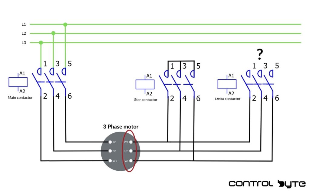
For a star junction setup, a contactor can be added with its power contacts wired to the terminals W2, U2, and V2.
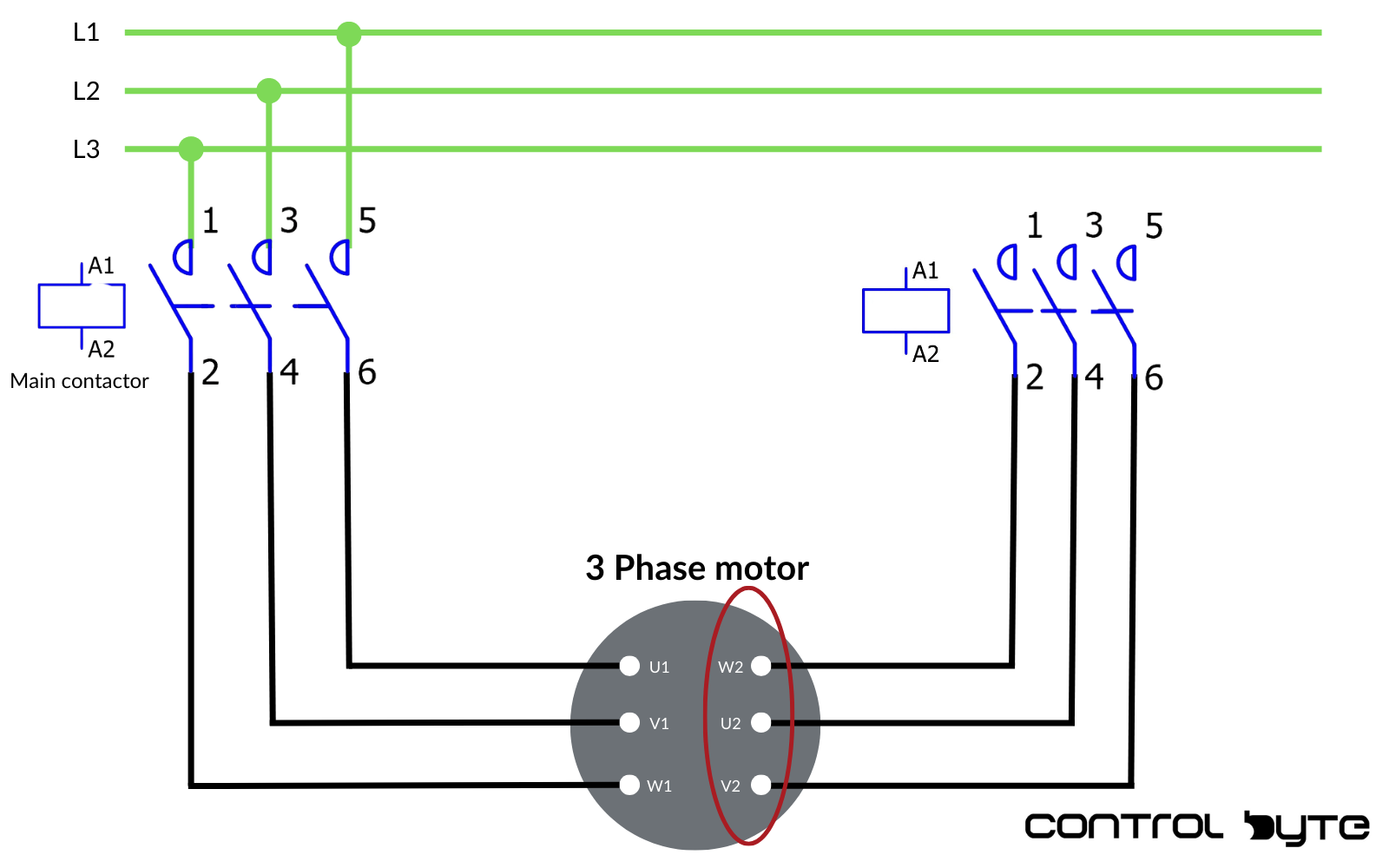
By short-circuiting the opposite ends of these contactor contacts, when they close, all three motor connection will connect, resulting in a star configuration.
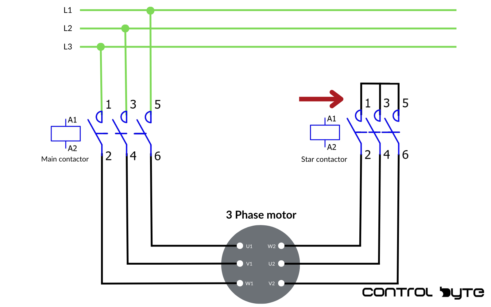
How Star and Main Contactors Coordinate for Efficient Motor Start-Up
In this arrangement, both the main and star contactors must be energized simultaneously to initiate the motor in a star connection.

Here, the main contactor supplies power to the motor, while the star contactor links the right-side motor terminals together, achieving the star configuration.

Switching to a Delta Connection with an Additional Contactor
To connect the motor windings in a delta configuration, an additional contactor, often called the three-phase contactor, is necessary. For this delta-connection, similar to the star configuration, the main contacts of the star-delta controller should be connected to the appropriate motor connection. This setup involves wiring the three main contacts to the right-side connection of the three phase motor, allowing for a seamless switch from star to delta as needed. Proper wiring and control of the delta contactor ensures that the motor operates efficiently in 3-phase delta mode, supporting optimal performance and reduced starting current.
Connecting Delta Contactor Ends to Power Phases
The other ends of the delta contactor’s contacts are then connected to L1, L2, and L3.

How to Activate Star and Delta Connections for Efficient Motor Control
With both the main and delta contactors activated and their contacts closed, U1 connects to W2, V1 to U2, and W1 to V2, forming the necessary delta winding configuration.

Therefore, when the main and star contactors are both engaged, the motor operates in star mode. Conversely, with the main and delta contactors energized, the motor operates in delta.

Controlling Contactors Using a PLC
These contactors lack physical buttons for manually opening or closing the contacts, making them reliant on external control circuits for proper operation. To activate these contactors and manage their switching functions, they need to be integrated with an industrial controller, such as a PLC. By connecting the contactor control circuit to the PLC, operators can achieve precise automation in switching between the star and delta configurations for a 3-phase motor.
Star-delta starter
This star-delta starter setup within the PLC allows for seamless management of contactor activation, enabling efficient control over the motor’s starting current. The PLC is programmed to send signals to each contactor in sequence, ensuring that the motor windings transition smoothly between the star and delta configurations without manual intervention. Using a PLC control circuit also provides flexibility in adjusting the timing for the switch from star to delta based on the motor’s load and speed requirements.
Integrating a PLC with contactors not only automates the motor’s operation but also increases the system’s reliability and safety by reducing the need for physical adjustments. In the upcoming lesson, we’ll dive into the steps required to program the PLC for controlling star-delta wiring and managing each contactor effectively, ensuring the 3-phase motor operates smoothly under varied load conditions. This automated control is essential for three phase motor systems that require regular switching between star and delta modes, particularly in industrial environments focused on motor protection and optimized performance.
Controlling Star to Delta Transition in Three-Phase Motor Starters with PLC
To efficiently control the transition from a star connection to a delta-connection in a three phase motor, a PLC control circuit plays a critical role. In a star-delta starter setup, the motor initially starts in a star configuration to reduce the starting current. This configuration lowers the initial load on the motor windings, ensuring the induction motor experiences less stress at start-up. Once the motor reaches a stable speed, the PLC automatically switches the wiring from star to delta, creating a smooth transition to a delta configuration. This diagram setup allows the 3-phase motor to achieve full operating power and efficiency while minimizing initial current draw. The control circuit thus ensures optimal performance, connecting each phase at the correct time for both star or delta modes and ensuring longevity for the three phase motor.
Thank you for reading!
Thank you for reading! If you’re interested in learning more, explore our courses for in-depth training: Control Byte Courses.


